Introduction
Use this step-by-step guide and video to help create the 3 LED/Control Box circuit. Complete this portion of the overall Flat Fish project FIRST.
Video Overview
-
-
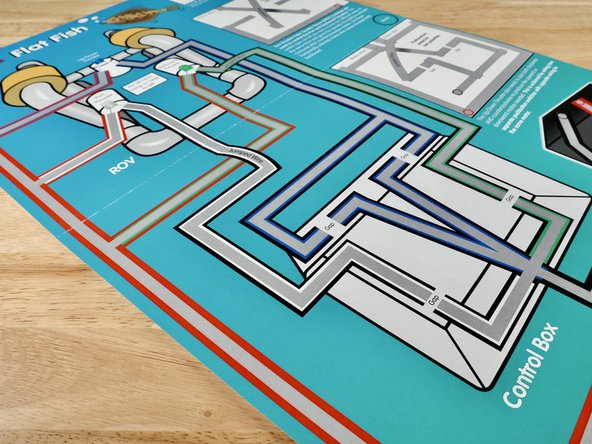
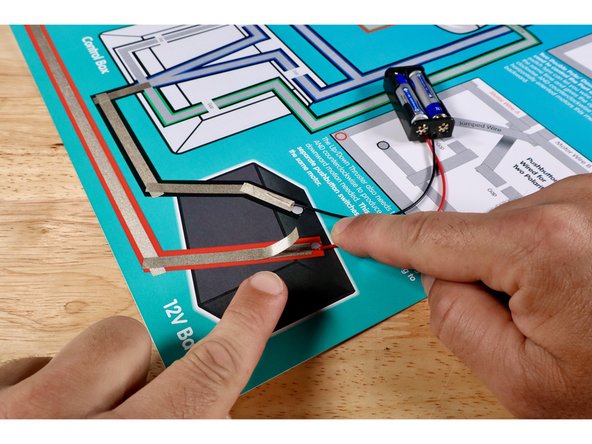
Real ROVs use bigger batteries like the one pictured on your poster. The red and black circles on that 12V Battery graphic are where Positive and Negative wires from your AAA battery packs will be connected instead.
-
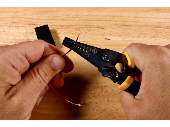
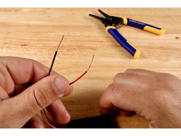
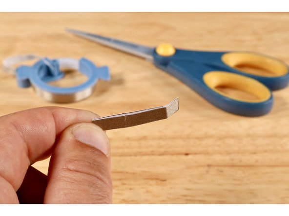
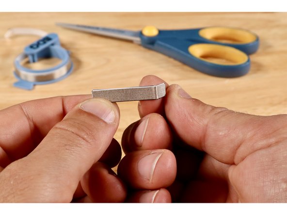
Use a wire strippers to strip away another 1/4"-1/2" of insulation from each of the two wires that lead from the body of the battery pack.
-
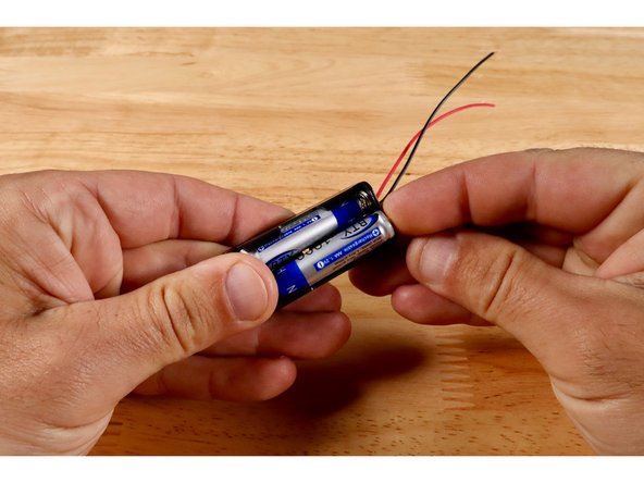
Finish preparing your battery pack by inserting 2X AAA NON-RECHARGEABLE batteries into the battery pack; making sure that they are each facing the correct way.
-
-
-
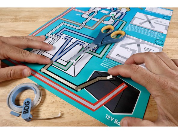
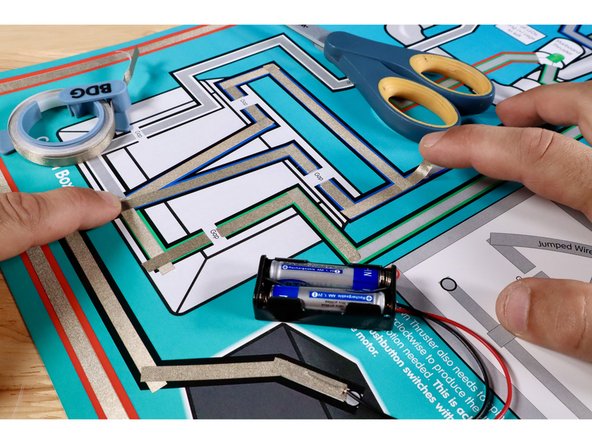
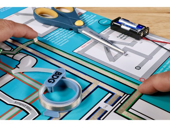
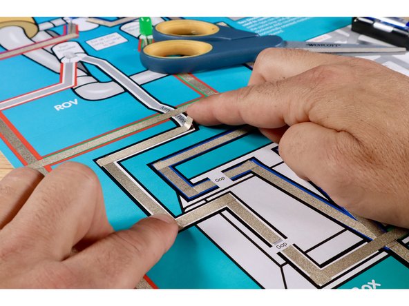
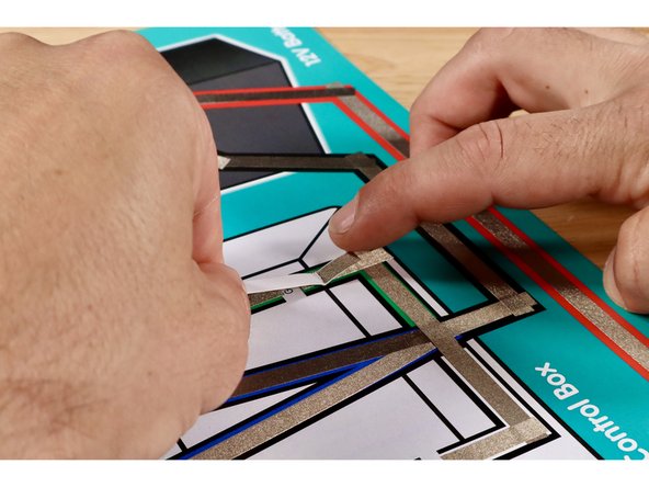
Measure, cut, peel, and stick the parts of the black Maker Tape path leading into the control box on the template. Overlap each segment as you go. From here, the flow of electricity will be split into several paths to feed the three outcomes at the ROV.
-
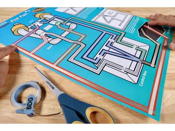
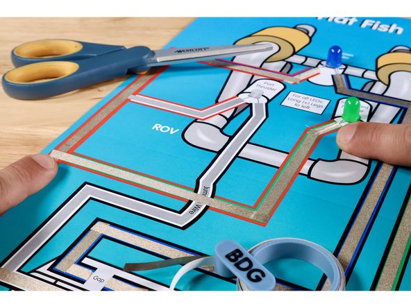
Measure, cut, peel, and stick parts of the red path leading from the ROV back TO the battery. Overlap each segment as you go.
-
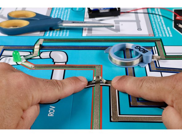
Cut two more small pieces of Maker Tape and use them to hold the red wire from the battery pack in contact with the red path and the black wire in contact with the black path.
-
-
-
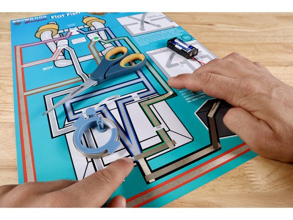
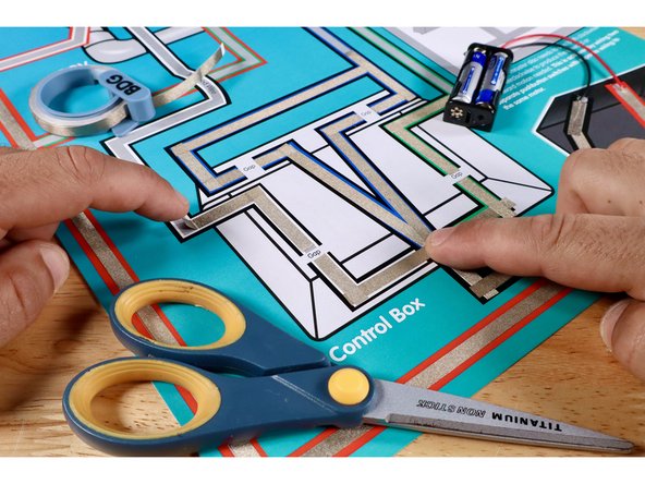
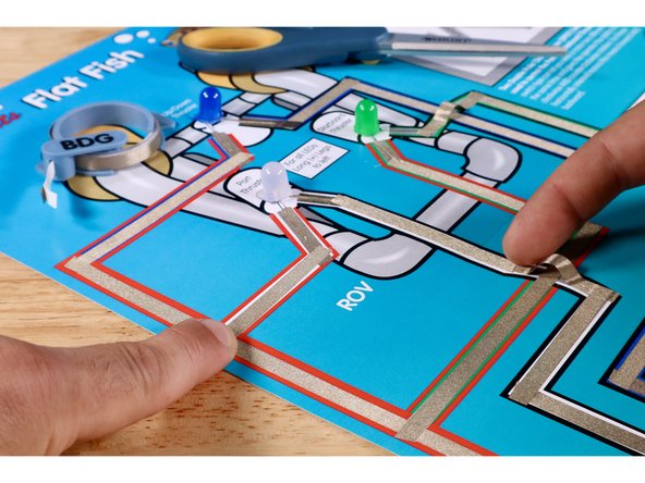
In the next steps, the flow of electricity will be split in the control box in order to power up three separate outcomes at the ROV. Each path is color-coded to match the color of an LED positioned on the ROV graphic. These LEDs represent the locations of motors called "thrusters" on a real ROV.
-
Measure, cut, peel, and stick the 4 Maker Tape paths shown to complete the green path out of the control box. Take care to leave a tape-free gap where shown.
-
Measure, cut, peel, and stick the 9 Maker Tape paths shown to complete the 2 branches of the blue path out of the control box. Take care to leave a tape-free gap where shown.
-
Measure, cut, peel, and stick the 4 Maker Tape paths shown to complete the white path out of the control box. Take care to leave a tape-free gap where shown.
-
-
-
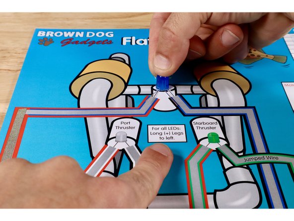
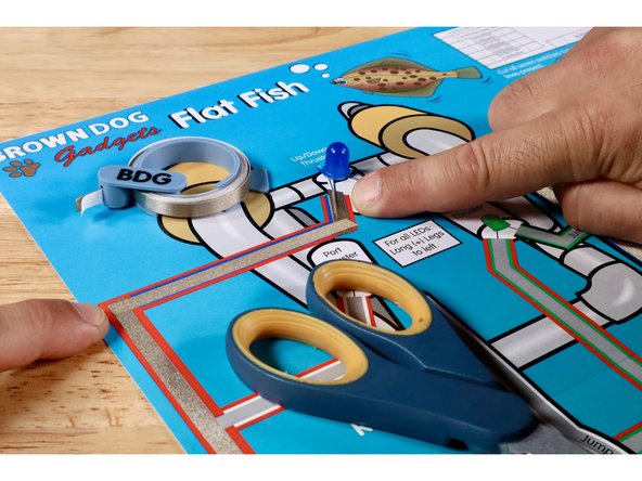
To prepare the Blue LED, first orient the legs so that the Long Positive (+) Leg is on the left. Next, fold the legs flat and then in a "V" so that it can sit in position atop the poster.
-
Measure, cut, peel, and stick the Maker Tape paths shown to complete the Blue LED/ROV outcome path. It should lead from the black/blue branch coming out of the control box, up to the short Negative (-) Leg of the Blue LED, then out the Long Positive (+) Leg of the Blue LED, and back to the Red Positive (+) Path leading back to the battery.
-
NOTE: The two Maker Tape Paths at each of the LED legs should go ON TOP of each of those LED legs.
-
-
-
To prepare the Green LED, first orient the legs so that the Long Positive (+) Leg is on the left. Next, fold the legs flat and then in a "V" so that it can sit in position atop the poster. NOTE: This step is not pictured. Use the same process used to prepare the Blue LED for this LED in ITS location.
-
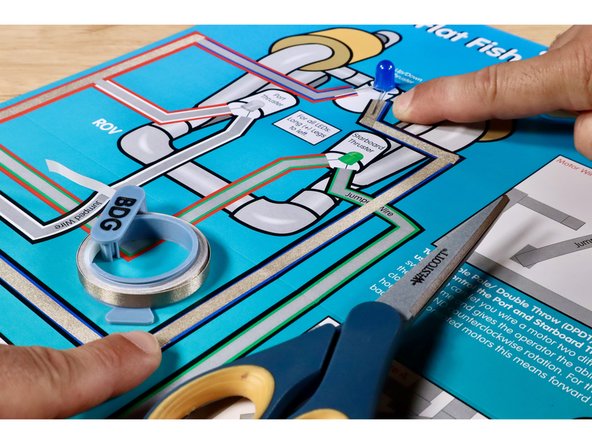
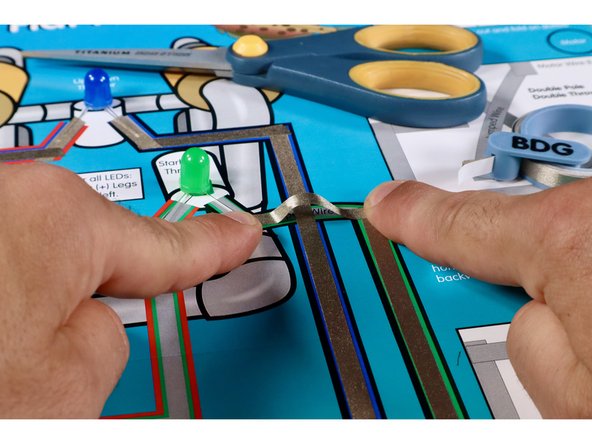
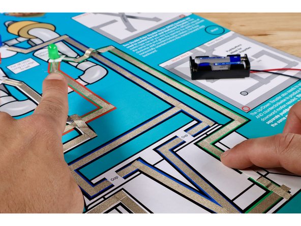
Measure, cut, peel, and stick the first Maker Tape path shown. It should lead from the Black Negative (-) Path coming out of the control box, up toward the Green LED.
-
The next Maker Tape path must jump OVER the Blue LED path without touching it. Use extra length when measuring to create the necessary slack to avoid contact with the path below.
-
Measure, cut, peel, and stick the remaining Maker Tape paths that are part of the Green LED/ROV outcome circuit until joining the Red Positive (+) Path back to the battery. NOTE: The two Maker Tape Paths at each of the LED legs should go ON TOP of each of those LED legs.
-
-
-
To prepare the White LED, first orient the legs so that the Long Positive (+) Leg is on the left. Next, fold the legs flat and then in a "V" so that it can sit in position atop the poster. NOTE: This step is not pictured. Use the same process used to prepare the Blue LED for this LED in ITS location.
-
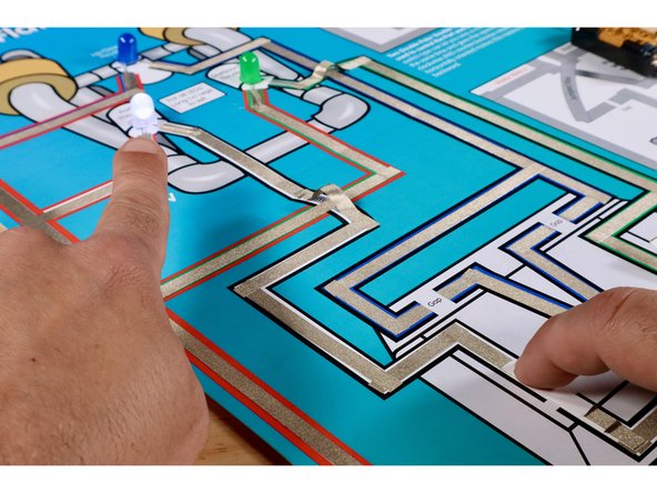
Measure, cut, peel, and stick the first two Maker Tape paths shown. They should lead from the Black Negative (-) Path coming out of the control box, up toward the White LED.
-
The next Maker Tape path must jump OVER the Green LED Path without touching it. Use extra length when measure to create the necessary slack to avoid contact with the path below.
-
Measure, cut, peel, and stick the remaining Maker Tape paths that are part of the White LED/ROV outcome circuit until joining the Red Positive (+) Path back to the battery. NOTE: The two Maker Tape Paths at each of the LED legs should go ON TOP of each of those LED legs.
-
-
-
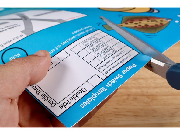
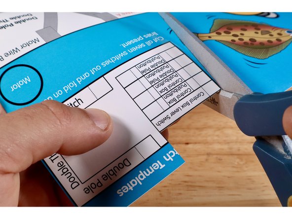
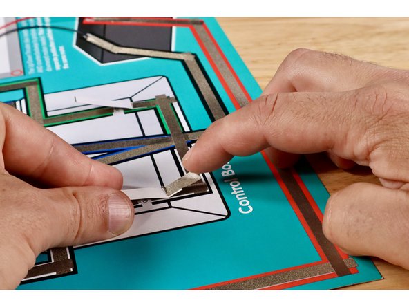
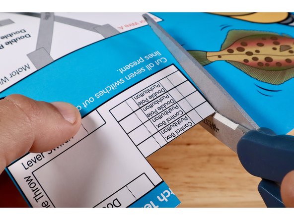
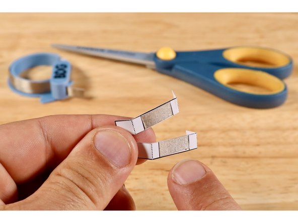
Cut and remove one of the "Control Box Lever Switch" templates from the upper right corner of the Flat Fish project poster. Fold it on the dotted line.
-
Measure, cut, peel, and stick a piece of Maker Tape where shown on the switch template.
-
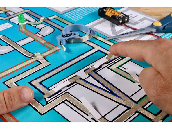
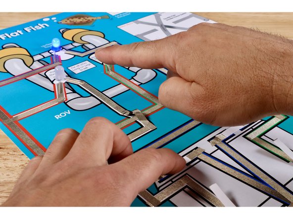
Install the switch by positioning it atop the gap (Maker Tape side down) where shown and securing it with another piece of Maker Tape. The fold should be atop the black horizontal line of the box graphic. The LED will now momentarily light up when the lever is pressed into contact with the upper part of the path across the gap.
-
-
-
Cut and remove the remaining "Control Box Lever Switch" template from the upper right corner of the Flat Fish project poster. Fold it on the dotted line.
-
Measure, cut, peel, and stick a piece of Maker Tape where shown on the switch template.
-
Install the switch by positioning it atop the gap (Maker Tape side down) where shown and securing it with another piece of Maker Tape. The fold should be atop the black horizontal line of the box graphic. The LED will now momentarily light up when the lever is pressed into contact with the upper part of the path across the gap.
-
-
-
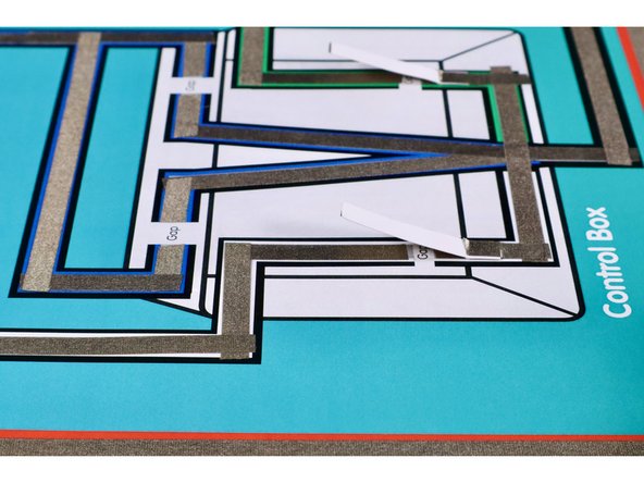
The images in this guide step are here simply to show the finished and working lever switches that were just installed.
-
-
-
Cut and remove the two "Control Box Pushbutton" templates from the upper right corner of the Flat Fish project poster. Fold each on the two dotted lines.
-
Measure, cut, peel, and stick a piece of Maker Tape where shown on each of the two switch templates.
-
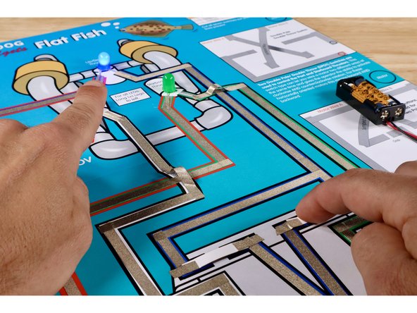
Install the switches by positioning them atop the gaps for the Blue LED/ROV outcome circuit (Maker Tape side down) while securing each with another 2 pieces of Maker Tape as shown. The LED should now momentarily light up when a given pushbutton is pressed.
-
-
-
The images in this guide step are here simply to show the finished and working pushbuttons that were just installed.
-
Wiring this circuit will give makers an idea of how power is routed into an ROV control box, where controls are, and which outcomes they affect. The circuit will also be used in Activity 2 to highlight the limitations of the switch types used when controlling MOTORS instead of LEDs.
Wiring this circuit will give makers an idea of how power is routed into an ROV control box, where controls are, and which outcomes they affect. The circuit will also be used in Activity 2 to highlight the limitations of the switch types used when controlling MOTORS instead of LEDs.