Introduction
Use this guide and video to create the "Double Pole Double Throw Switch" circuit wired to a motor. This explains an improvement on the basic control box.
Video Overview
Featured Document
-
-
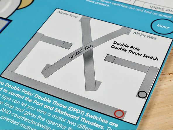
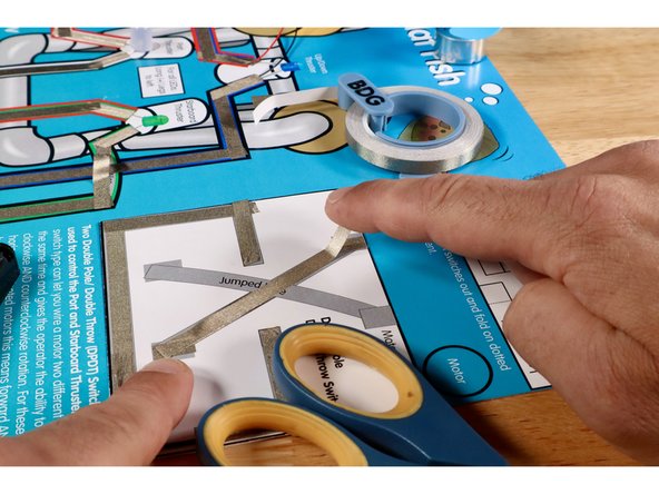
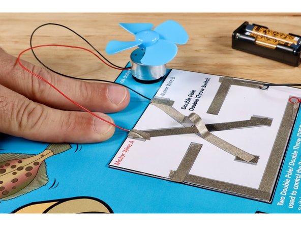
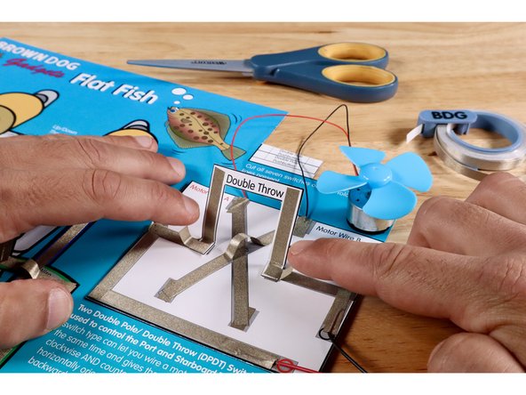
Locate the project template labeled "Double Pole Double Throw Switch". It is located on the upper half of the right hand side of the Flat Fish project poster.
-
Measure, cut, peel, and stick Maker Tape paths shown in the first image. The Negative (-) Black Circle Path will bring electricity into the switch. The Positive (+) Red Circle Path will allow the current to return to the voltage source.
-
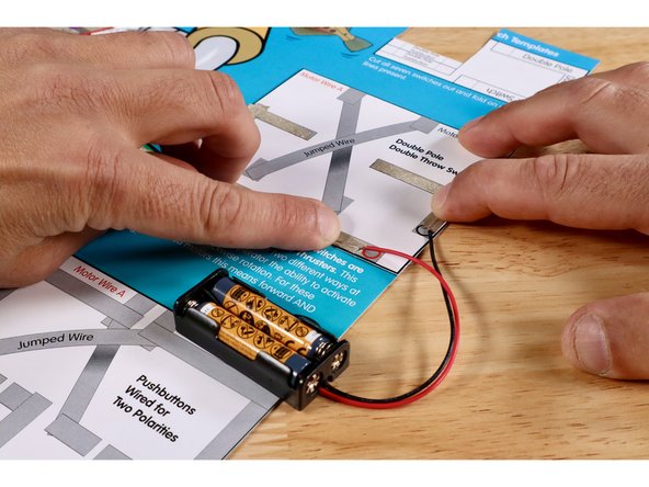
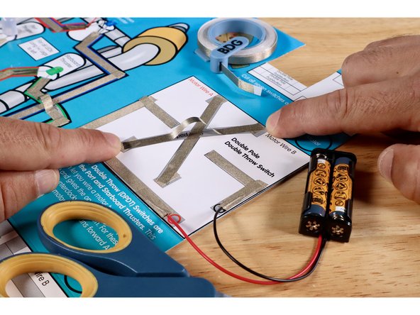
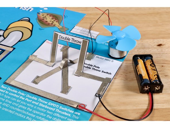
Remove the battery pack from your first circuit.
-
Using 2 small pieces of Maker Tape and the colored circle designators as guides, connect each of the battery pack wires to the appropriate paths on this new circuit template. The Maker Tape may still be reuse-able from the first circuit but it's fine to cut and use new pieces.
-
-
-
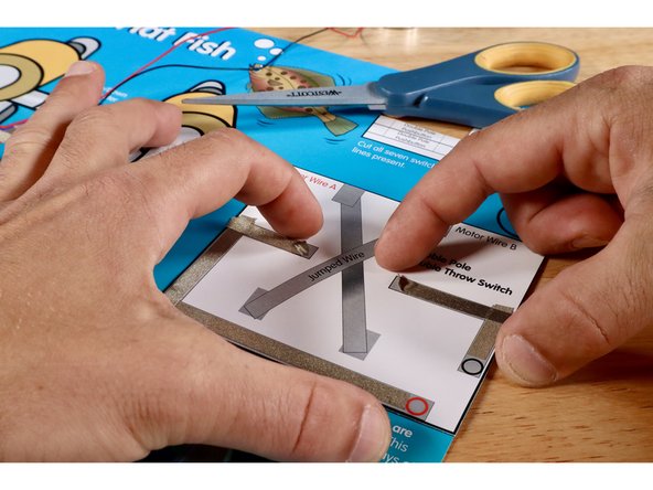
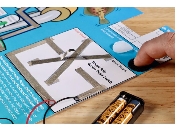
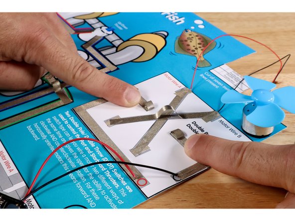
Measure, cut, peel, and stick the three Maker Tape segments that make up the lower part of the criss-cross.
-
Measure, cut, peel, and stick the Maker Tape segments of the upper part of the criss-cross. This involves a jumped wire just like you saw in the Green and White LED/ROV Outcome paths. Use extra length to enable this path to cross over and above the lower part without touching it.
-
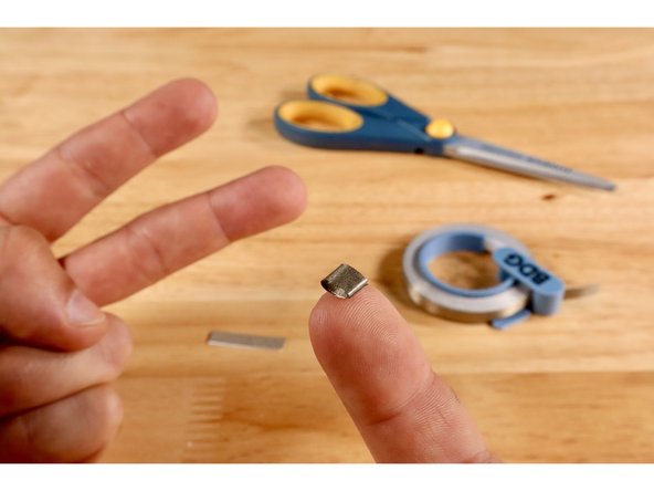
Peel and stick the fuzzy half of one of your hook and loop dots onto the circle labeled "motor"
-
-
-
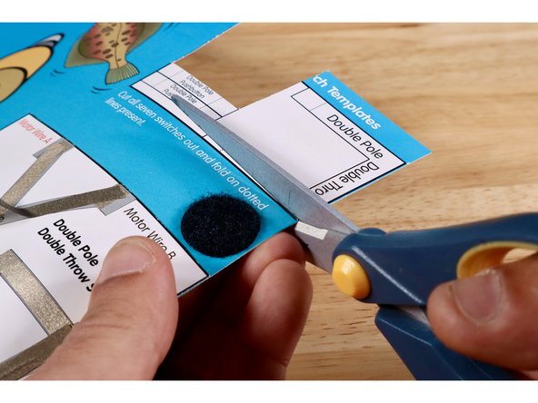
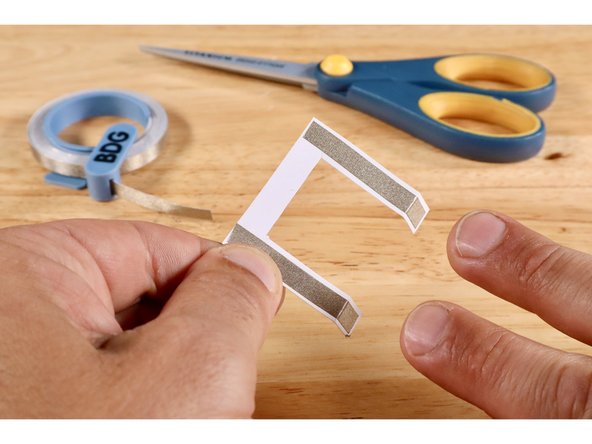
Cut and remove the U-shaped switch lever template labeled "Double Pole Double Throw Lever Switch" from the switch template bank located in the upper right hand corner of the Flat Fish project poster.
-
Fold the two dotted lines in the same direction.
-
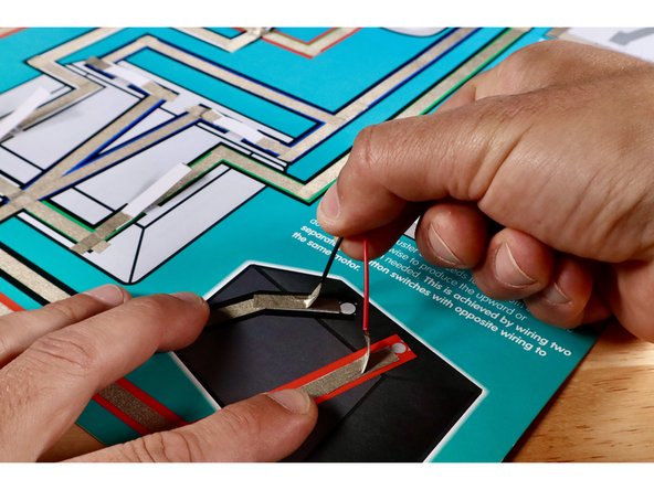
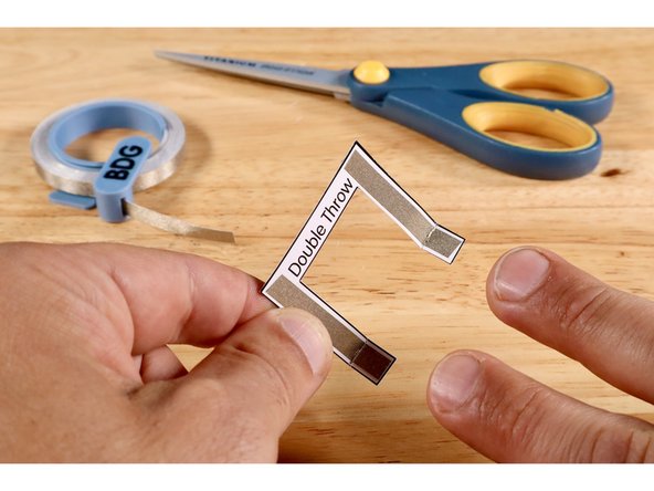
Measure, cut, peel, and stick Maker Tape paths where shown on Side One of the switch lever.
-
Measure, cut, peel, and stick Maker Tape paths where shown on Side Two of the switch lever.
-
-
-
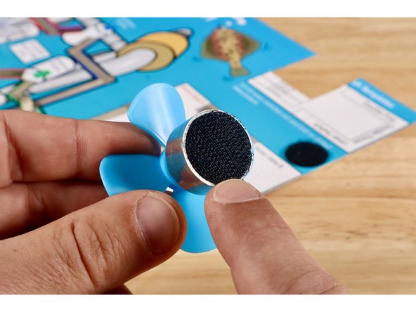
Peel and stick the hook half of that dot to the back of your motor.
-
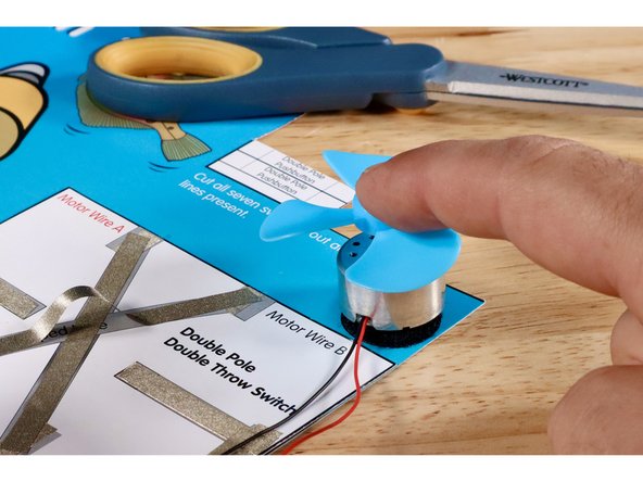
Now mount the motor and fan to the dot.
-
Connect the black motor wire to the end of the upper part of the criss-cross nearest to the "Motor Wire B" label. Use a small piece of Maker Tape that you measure, cut, peel, and stick as shown.
-
Connect the red motor wire to the end of the lower part of the criss-cross nearest to the "Motor Wire A" label. Use a small piece of Maker Tape that you measure, cut, peel, and stick as shown.
-
-
-
Cut two small pieces of Maker Tape and roll them into two sticky-side-out tape loops.
-
Stick the tape loops atop the ends of the voltage paths as shown.
-
-
-
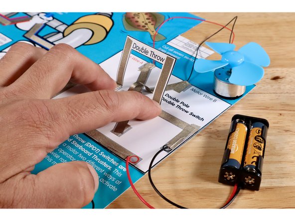
Press the folded squares of the switch lever to the Maker Tape loops you just stuck to the ends of the voltage paths. One side of the lever is now in contact with the rest of the circuit.
-
Cut, peel, and stick each of two small pieces of Maker Tape so half contacts the top of the square portion on the lever and the rest contacts the voltage path nearest to it. The opposite side of the lever is now in contact with the rest of the circuit.
-
-
-
Push the lever all the way forward into contact with the contact points below. Observe the direction of rotation at the motor.
-
Pull the lever all the way back into contact with the contact points below. Observe the direction of rotation at the motor.
-
-
-
Use the student sheet attached at the bottom of this guide to help assess comprehension. There is an educator copy as well.
-
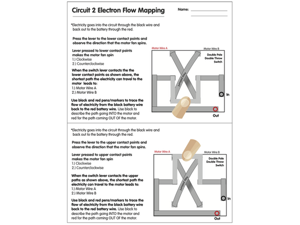
Completing and testing this circuit/switch type shows an improvement typically used to control green and white thruster paths on the first circuit. Now the outcomes can be motors instead of LEDs and they can be made to go both forward AND backward instead of just on and off "one way". When those two motors are oriented like they are on the ROV graphic, it can go forward, backward AND left/right. Use attached worksheets to assess comprehension!
Completing and testing this circuit/switch type shows an improvement typically used to control green and white thruster paths on the first circuit. Now the outcomes can be motors instead of LEDs and they can be made to go both forward AND backward instead of just on and off "one way". When those two motors are oriented like they are on the ROV graphic, it can go forward, backward AND left/right. Use attached worksheets to assess comprehension!