Video Overview
Featured Document
-
-
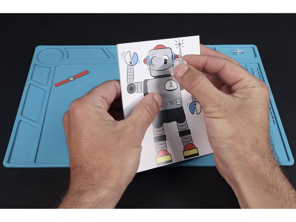
Press on the belt buckle to bring the conductive tape on the back of it into contact with the two small tape chunks on the card below.
-
-
-
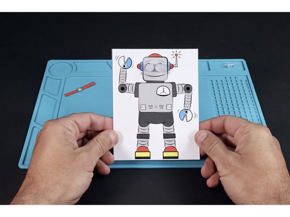
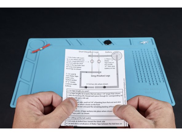
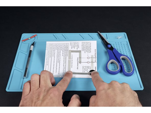
Print out the template and gather the listed tools and materials.
-
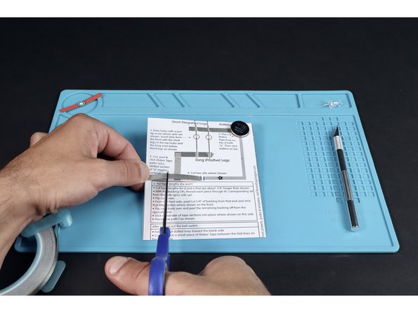
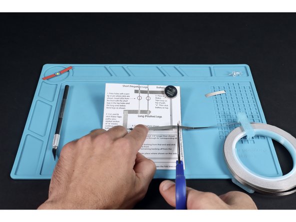
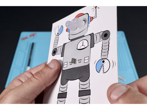
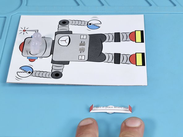
Cut along bottom line to separate belt from robot.
-
Take your time and cut belt out. Set aside.
-
-
-
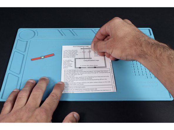
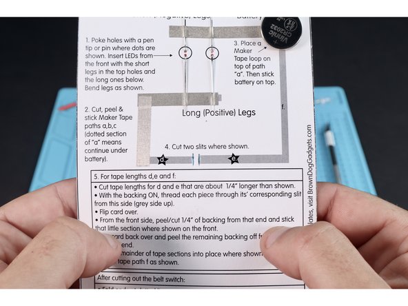
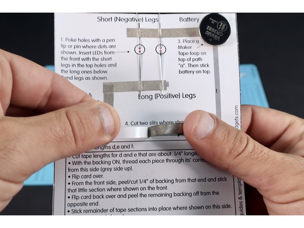
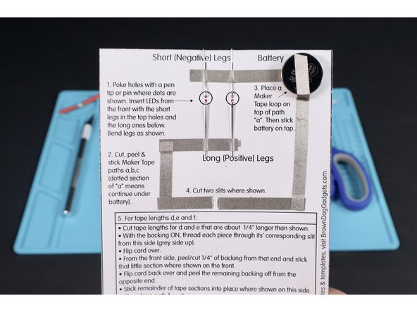
Using a thumbtack or push pin, poke holes where shown, using the 4 small dots as a guide.
-
Each vertical column of dots is a place to feed a single LEDs legs through. Feed the legs of each of the LEDs through their pair of holes from the front. Make sure to feed the short legs through the topmost holes and the longer legs through the lower holes.
-
-
-
Bend the legs of the two LEDs in opposite directions as shown.
-
-
-
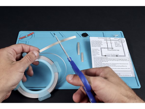
Measure and cut Maker Tape sections for tape paths "a","b" and "c".
-
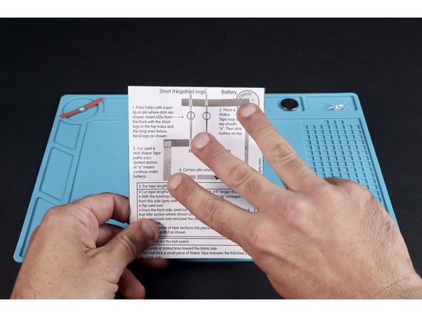
Stick those three tape sections into place where shown for pathways a,b,c. Tape paths "a" and "b" go OVER the LED legs.
-
-
-
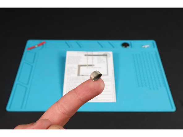
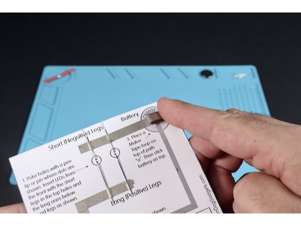
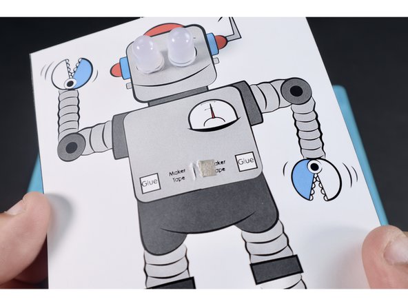
Cut a short length of Maker Tape and roll it into a loop (sticky side out).
-
Stick that loop onto existing tape path "a".
-
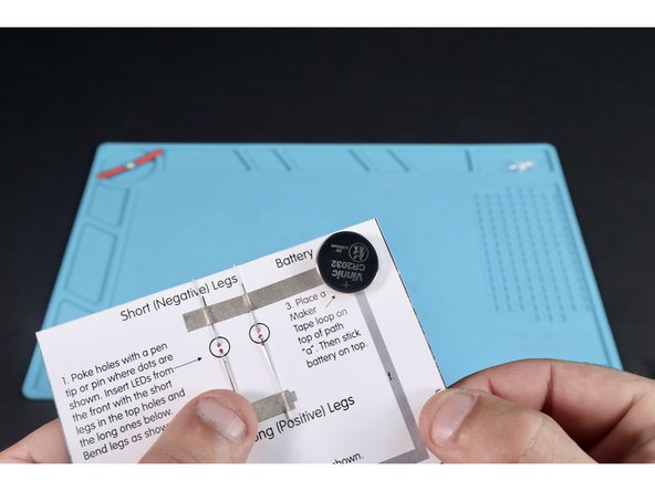
Stick your battery (positive side up) onto the tape loop.
-
-
-
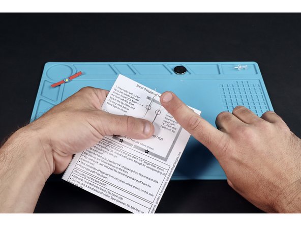
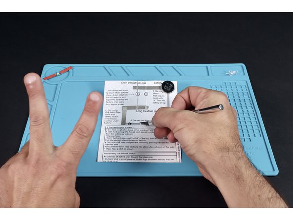
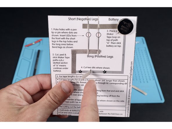
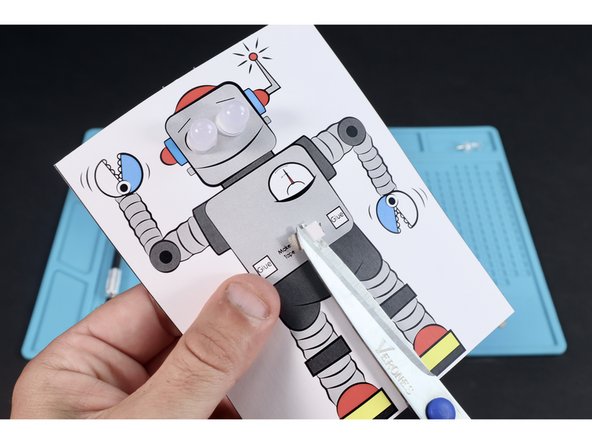
Using an X-ACTO/Craft knife, cut the two small vertical slits shown between paths "d" and "e". Be careful to maintain the paper gap between them.
-
-
-
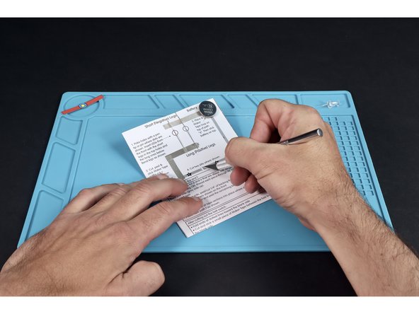
Measure and cut the tape length for path "d" so it is about 1/4" longer than shown.
-
Measure and cut the tape length for path "e" so it's also about 1/4" longer than shown.
-
With the backing kept ON, thread the tape section for "d" through its' slot from the back so the backing faces left and the tape faces right as shown.
-
-
-
Turn card over. Adjust how much of section "d" is threaded through so that only that 1/4" excess is showing.
-
Peel the backing of that excess and cut to reveal the sticky side.
-
Stick that little section down atop the nearest of the two areas labeled "Maker Tape". When finished it should look like photo 3 and have the remainder of the tape path hanging out of the back side with the backing still on it.
-
-
-
Flip card to back and peel the backing from the remainder of path "d". Stick into place where shown. Repeat the entire process you used for path "d" for path "e".
-
Measure, cut and stick path "f" in place so that the upper section is atop the battery. Your finished circuit should look like the last photo.
-
-
-
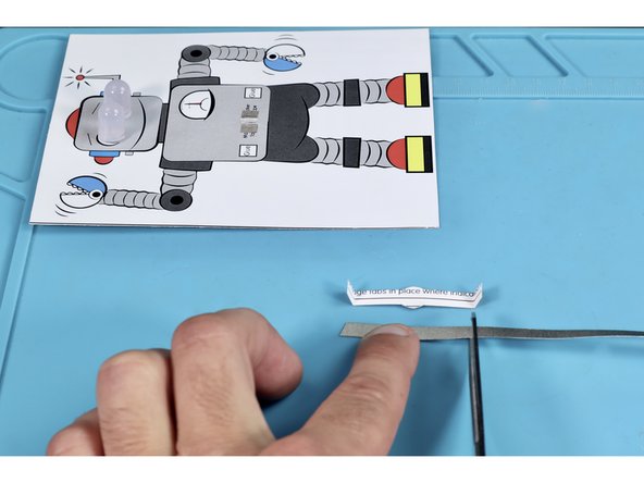
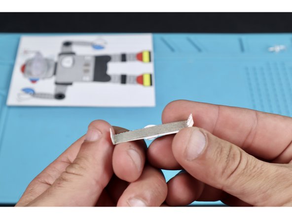
Fold the edges of the belt on the dotted lines found on the font of the belt. Fold AWAY from the front TOWARD the back.
-
Measure, cut and stick a piece of Maker Tape on the back between the two new fold lines.
-
-
-
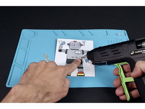
With a glue gun, apply a small dot of glue where indicated in the first photo.
-
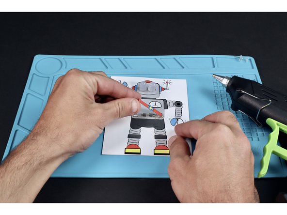
With the belt faced UP, lay the "x" side of one of the edge tabs in the glue and wait for the glue to cool. Note: Use a pencil or popsicle stick instead of your finger if you feel the need to press the tab into the glue.
-
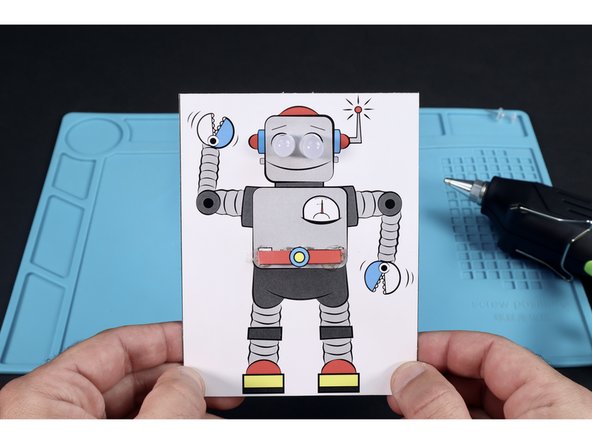
Repeat the process for the last tab so that the belt looks like the final photo. If done correctly, the conductive portion of the back will NOT lay flat against the rest of the card. Pushing the buckle down into contact with the two small Maker Tape nubs will complete the circuit and turn the LED eyes on.
-