
Introduction
Connect an LED to a Bit Board and control it with a micro:bit
We'll make the LED fade from off to the full brightness in steps using PWM (Pulse Width Modulation).
Video Overview
Featured Document
-
-
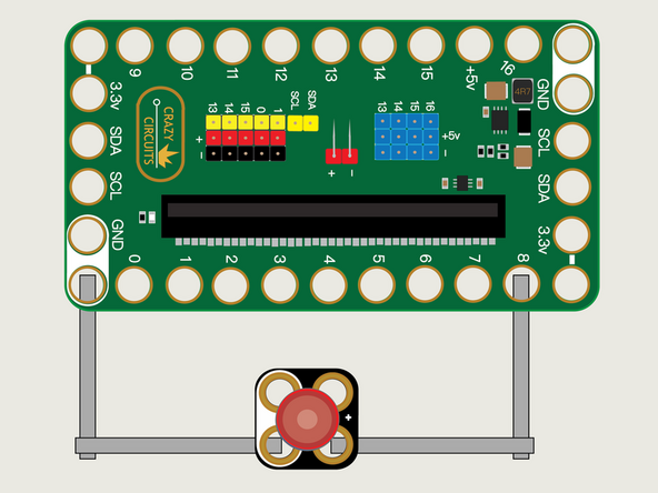
We'll use Maker Tape to connect the LED to the Bit Board on a LEGO baseplate.
-
Connect the Negative (-) side of the LED to a Ground (GND) hole on the Bit Board.
-
Connect the Positive (+) side of the LED to Pin 8 on the Bit Board.
-
You'll notice the Ground on the Bit Board (as well as the LED and other Crazy Circuits components we'll use) is color coded White.
-
-
-
If you've never used a micro:bit before you'll want to check out this guide: Bit Board V2 Setup and Use
-
We're going to load the following code for our LED Fade program: https://makecode.microbit.org/_ArzM1u7Lt...
-
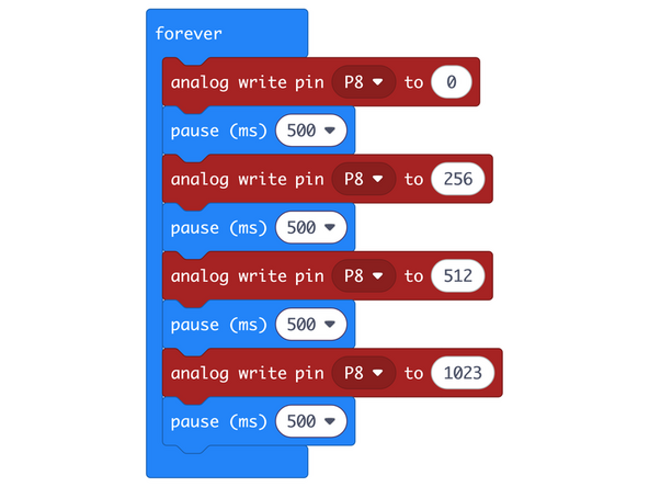
This code will make the LED gradually get brighter waiting a half second between each step.
-
The analog write command can be set to anything between 0 (off) and 1023 (full brightness).
-
We can choose which pin will be affected using the drop down control in the analog write command. Here it is set to Pin 8.
-
While digital write allowed us to turn an LED on or off, analog write allows for more control over the brightness of the LED.
-
-
-
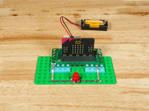
Once the code is loaded it should start running immediately.
-
You can power the micro:bit via the USB cable you used to load the code or you can use a battery pack plugged into the Bit Board.
-
The LED should start off then get gradually brighter in three steps.
-
-
-
Follow along with our recorded Live Stream!
-
You can watch the full video of us walking through this project, along with explaining and exploring the code: https://youtube.com/live/z8ONp1Q9ZV0
-
Attached Documents
