
Introduction
Connect a potentiometer to a Bit Board and control the micro:bit's built-in LED matrix.
We'll explore how we can use a potentiometer as an input for the micro:bit
Video Overview
Featured Document
-
-
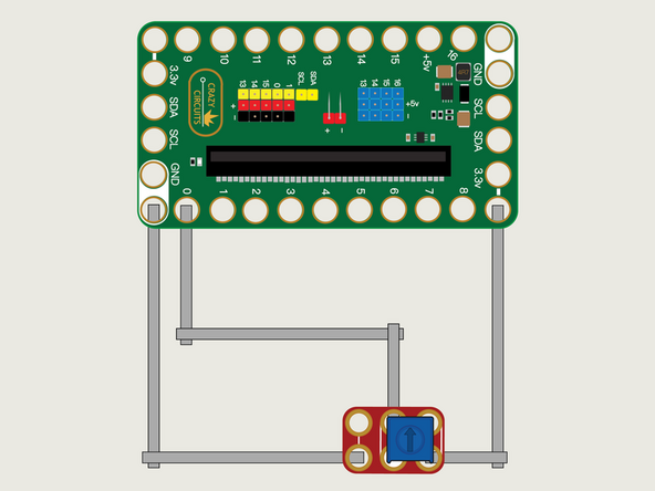
We'll use Maker Tape to connect the Potentiometer to the Bit Board on a LEGO baseplate.
-
We'll need to connect one side of the Potentiometer to Ground (GND) and the other side to 3.3v
-
We will then connect the center of the Potentiometer to Pin 0. (Note that Pin 0 is an analog pin, which we'll need for the Potentiometer.)
-
The other analog pins are 1, 2, 3, 4, and 10. See this chart for a pinout diagram: https://makecode.microbit.org/device/pin...
-
You'll notice the Ground on the Bit Board is color coded White.
-
The 3.3v hole on the Bit Board is labeled and is actually two holes right next to each other on the Bit Board. (There is a small line showing the connection between them.)
-
-
-
If you've never used a micro:bit before you'll want to check out this guide: Bit Board V2 Setup and Use
-
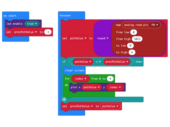
We're going to load the following code for our Potentiometer Line Smooth program: https://makecode.microbit.org/_hTPboEafb...
-
This code is similar to our previous example, but we've added a for loop to plot a vertical line rather than just a single pixel.
-
We could have easily added four more plot commands and hardcoded the y value but a loop is a bit less code in this case.
-
-
-
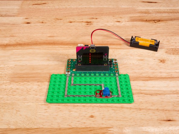
Once the code is loaded it should start running immediately.
-
You can power the micro:bit via the USB cable you used to load the code or you can use a battery pack plugged into the Bit Board.
-
Turn the small blue knob on the Potentiometer and you should see a column of 5 pixel move left or right.
-
Could you easily modify this code to make a horizontal line go up and down instead?
-
-
-
Follow along with our recorded Live Stream!
-
You can watch the full video of us walking through this project, along with explaining and exploring the code: https://youtube.com/live/jN7oP8TrU8k
-
Attached Documents
