Introduction
Connect a potentiometer to a Bit Board and control an LED.
We'll explore how we can use a potentiometer as an input for the micro:bit and control the output of an LED.
Video Overview
Featured Document
-
-
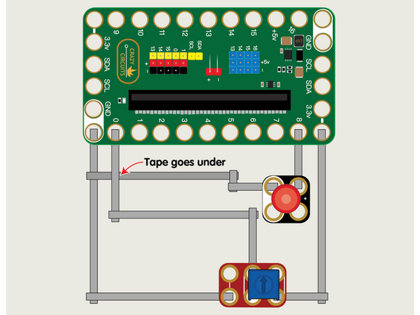
We'll use Maker Tape to connect the Potentiometer and LED to the Bit Board on a LEGO baseplate.
-
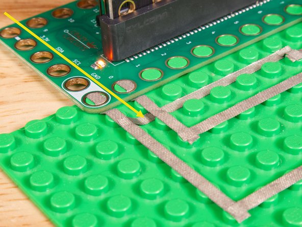
The LED will connect to Pin 8 and to Ground (GND) BUT! We're going to use the "gutter" between the LEGO baseplate studs so we can have two layers of tape that do not touch.
-
See the photos to show how this works. It's a technique we'll use for certain projects. It can also be used when you're tight on space for tape paths.
-
Once the LED is connected we'll need to connect the Potentiometer. One side goes to Ground (GND) and the other side to 3.3v
-
We will then connect the center of the Potentiometer to Pin 0. (Note that Pin 0 is an analog pin.)
-
You'll notice the Ground on the Bit Board is color coded White.
-
The 3.3v hole on the Bit Board is labeled and is actually two holes right next to each other on the Bit Board. (There is a small line showing the connection between them.)
-
-
-
If you've never used a micro:bit before you'll want to check out this guide: Bit Board V2 Setup and Use
-
We're going to load the following code for our Potentiometer LED Bright program: https://makecode.microbit.org/_Fg09D1Vqh...
-
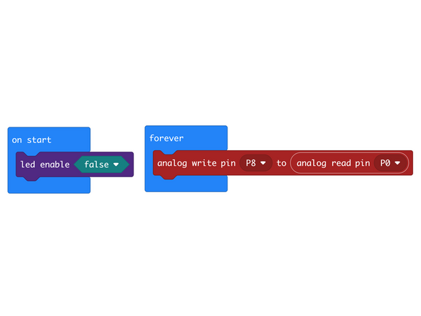
Our code is pretty simple! We'll first turn off the built-in led because we don't need it, then we'll forever loop an analog write to Pin 8 (which is where we connected the LED) and set the value we get from the Potentiometer connected to Pin 0.
-
The Potentiometer provides a value between 0 and 1023, and the LED can accept a value between 0 (off) and 1023 (full brightness) so we don't even need to constraint or map the values.
-
Some microcontrollers are limited to a range of 0-255 for PWM (Pulse Width Modulation) output, or what we call analog write, but the micro:bit can use 0-1023.
-
-
-
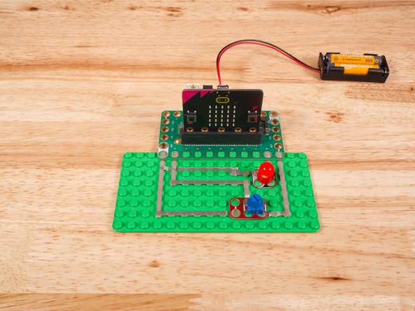
Once the code is loaded it should start running immediately.
-
You can power the micro:bit via the USB cable you used to load the code or you can use a battery pack plugged into the Bit Board.
-
Turn the small blue knob on the Potentiometer and you'll see the brightness of the LED change.
-
Turning fully anti-clockwise should make the LED so dim it appear to be "off" and turning the knob fully clockwise should set it to the brightest it can go.
-
-
-
Follow along with our recorded Live Stream!
-
You can watch the full video of us walking through this project, along with explaining and exploring the code: https://youtube.com/live/1FlnatERZ94
-

Attached Documents
