Introduction
Connect a potentiometer to a Bit Board and control an LED.
We'll explore how we can use a potentiometer as an input for the micro:bit and control the output of an LED.
Video Overview
Featured Document
-
-
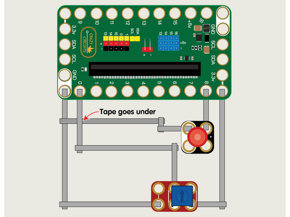
We'll use Maker Tape to connect the Potentiometer and LED to the Bit Board on a LEGO baseplate.
-
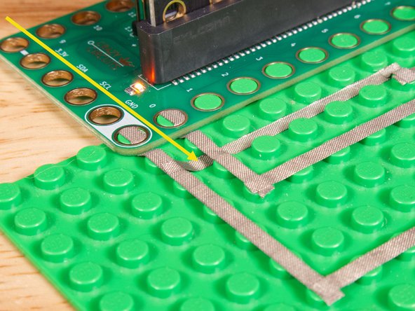
The LED will connect to Pin 8 and to Ground (GND) BUT! We're going to use the "gutter" between the LEGO baseplate studs so we can have two layers of tape that do not touch.
-
See the photos to show how this works. It's a technique we'll use for certain projects. It can also be used when you're tight on space for tape paths.
-
Once the LED is connected we'll need to connect the Potentiometer. One side goes to Ground (GND) and the other side to 3.3v
-
We will then connect the center of the Potentiometer to Pin 0. (Note that Pin 0 is an analog pin.)
-
You'll notice the Ground on the Bit Board is color coded White.
-
The 3.3v hole on the Bit Board is labeled and is actually two holes right next to each other on the Bit Board. (There is a small line showing the connection between them.)
-
-
-
If you've never used a micro:bit before you'll want to check out this guide: Bit Board V2 Setup and Use
-
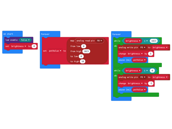
We're going to load the following code for our Potentiometer LED Fade program: https://makecode.microbit.org/_2D0Fd81hq...
-
Our code will use two forever loops, that will run concurrently. One will capture the input from the Potentiometer and store it in the potValue variable, and the second will fade the LED up and then down in brightness, using our potValue to adjust the speed of the fade.
-
-
-
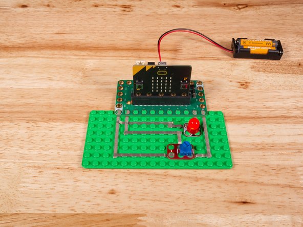
Once the code is loaded it should start running immediately.
-
You can power the micro:bit via the USB cable you used to load the code or you can use a battery pack plugged into the Bit Board.
-
Turn the small blue knob on the Potentiometer and you'll see the LED fading up and/or down and the rate of the fading will change depending on the position of the knob.
-
-
-
Follow along with our recorded Live Stream!
-
You can watch the full video of us walking through this project, along with explaining and exploring the code: https://youtube.com/live/1FlnatERZ94
-

Attached Documents
