Introduction
Connect a Crazy Circuits NeoPixel to a Bit Board and control it with code.
We'll explore how to control an RGB LED (a "NeoPixel") for a bit more color from our LEDs.
Video Overview
Featured Document
-
-
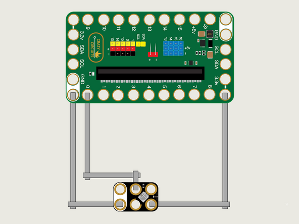
We'll use Maker Tape to connect the NeoPixel to the Bit Board on a LEGO baseplate.
-
To connect the NeoPixel, one side goes to Ground (GND) and the other side to 3.3v
-
We'll then connect the center pin labeled DI (for Digital Input) to Pin 0, which will control the NeoPixel.
-
A NeoPixel is a "Smart LED" which is actually three LEDs (a red, green, and blue LED).
-
You'll notice the Ground on the Bit Board (as well as the NeoPixel and other Crazy Circuits components we'll use) is color coded White.
-
The 3.3v hole on the Bit Board is labeled and is actually two holes right next to each other on the Bit Board. (There is a small line showing the connection between them.)
-
-
-
If you've never used a micro:bit before you'll want to check out this guide: Bit Board V2 Setup and Use
-
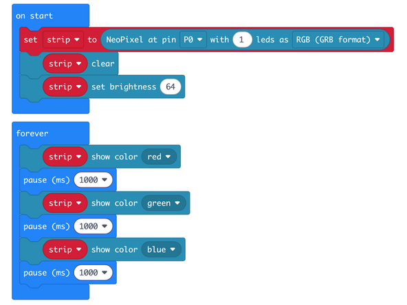
We're going to load the following code for our NeoPixel RGB program: https://makecode.microbit.org/_8YbArTcCX...
-
The NeoPixel extension allows us to control the NeoPixel. In this example we'll just set it up and set it to different colors; red, then green, then blue.
-
-
-
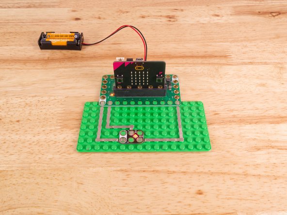
Once the code is loaded it should start running immediately.
-
You can power the micro:bit via the USB cable you used to load the code or you can use a battery pack plugged into the Bit Board.
-
You'll see the NeoPixel cycle through red, green, and blue in a loop, pausing one second after each color change.
-
-
-
Follow along with our recorded Live Stream!
-
You can watch the full video of us walking through this project, along with explaining and exploring the code: https://youtube.com/live/DL4SOdBmF5w
-

Attached Documents
