Introduction
Connect a 270˚ Servo to a Bit Board and control it with a Potentiometer and code.
We'll explore using a potentiometer (and some code) to control the movement of a servo motor.
Video Overview
Featured Document
-
-
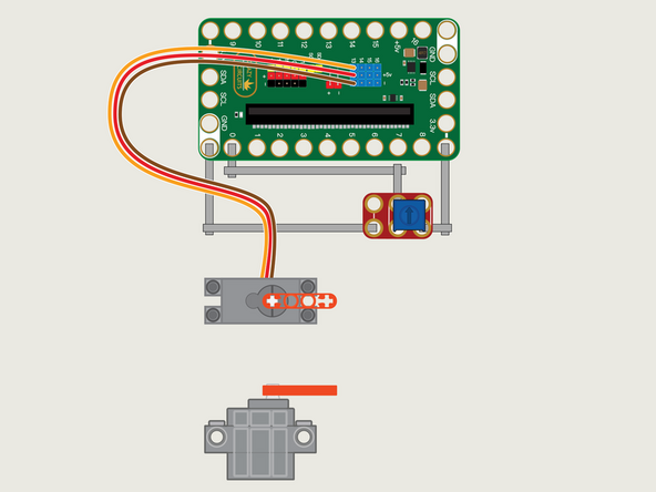
The 270 Degree Servo Motor has a 3-wire connector on the end that can plug directly into the pins on the back of the Bit Board.
-
Make sure the Orange Wire is closest to the number 13 for the Pin 13 column.
-
Then the Brown Wire should be closest to the micro:bit (in the - row) and the Red Wire will be in the middle (the +5v row).
-
We'll need to connect one side of the Potentiometer to Ground (GND) and the other side to 3.3v
-
We will then connect the center of the Potentiometer to Pin 0. (Note that Pin 0 is an analog pin, which we'll need for the Potentiometer.)
-
The other analog pins are 1, 2, 3, 4, and 10. See this chart for a pinout diagram: https://makecode.microbit.org/device/pin...
-
You'll notice the Ground on the Bit Board is color coded White.
-
The 3.3v hole on the Bit Board is labeled and is actually two holes right next to each other on the Bit Board. (There is a small line showing the connection between them.)
-
-
-
If you've never used a micro:bit before you'll want to check out this guide: Bit Board V2 Setup and Use
-
We're going to load the following code for our Servo Potentiometer Step program: https://makecode.microbit.org/_CgYJieX9Y...
-
Our Potentiometer will function like a four-position rotary switch.
-
The code will check the value of the Potentiometer and determine what angle to set the Servo based on the potVal variable.
-
Where does the 60 come from? If we divide 180 by 4 we get 45... but we need to divide 180 by 3 because we also need the 0 (zero) position, so 180 / 3 = 60.
-
We do (almost) the same thing with the Potentiometer value, though the math gets tricky because 0 to 1023 is 1024 values, so when we count the first 256 values we use 0 to 255. (Math gets weird when you include zero)
-
-
-
Once the code is loaded it should start running immediately.
-
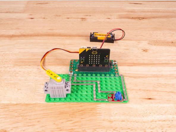
You can power the micro:bit via the USB cable you used to load the code, but now that we are using servos we recommend using a battery pack plugged into the Bit Board.
-
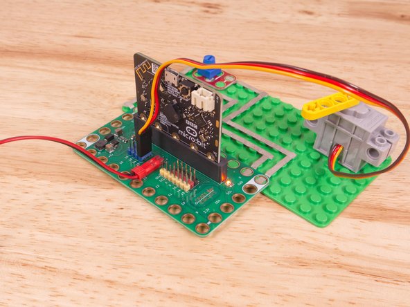
The Blue Pins on the Bit Board provide extra power (5 volts instead of 3 volts) by boosting the voltage coming from the battery pack. This helps improve servo performance, especially with multiple servos.
-
Turn the Potentiometer dial to move the Servo to one of four different positions/angles.
-
-
-
Follow along with our recorded Live Stream!
-
You can watch the full video of us walking through this project, along with explaining and exploring the code: https://youtube.com/live/7ulebPcKk2A
-


Attached Documents
