
Introduction
Connect a 360˚ Servo to a Bit Board and control it with a Potentiometer and code.
We'll explore code to control the movement of a continuous rotation (360 degree) servo motor using a potentiometer.
Video Overview
Featured Document
-
-
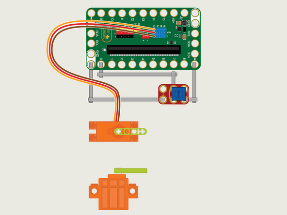
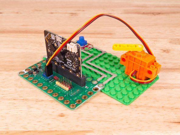
The 360 Degree Servo Motor has a 3-wire connector on the end that can plug directly into the pins on the back of the Bit Board.
-
Make sure the Orange Wire is closest to the number 13 for the Pin 13 column.
-
Then the Brown Wire should be closest to the micro:bit (in the - row) and the Red Wire will be in the middle (the +5v row).
-
We'll need to connect one side of the Potentiometer to Ground (GND) and the other side to 3.3v
-
We will then connect the center of the Potentiometer to Pin 0. (Note that Pin 0 is an analog pin, which we'll need for the Potentiometer.)
-
The other analog pins are 1, 2, 3, 4, and 10. See this chart for a pinout diagram: https://makecode.microbit.org/device/pin...
-
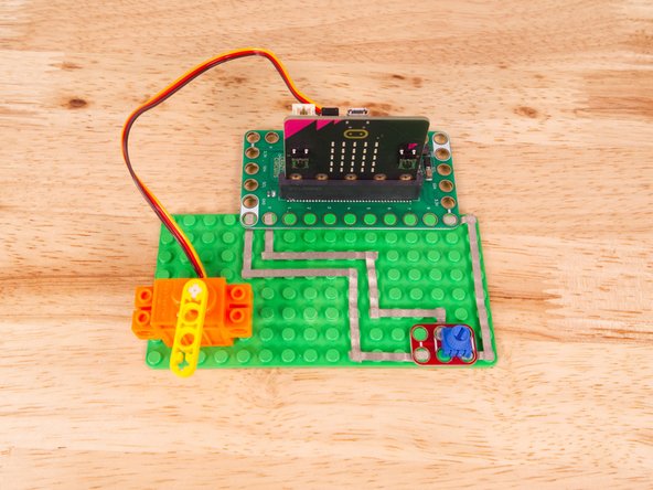
You'll notice the Ground on the Bit Board is color coded White.
-
The 3.3v hole on the Bit Board is labeled and is actually two holes right next to each other on the Bit Board. (There is a small line showing the connection between them.)
-
-
-
If you've never used a micro:bit before you'll want to check out this guide: Bit Board V2 Setup and Use
-
We're going to load the following code for our 360 Servo Potentiometer Speed program: https://makecode.microbit.org/_Rmv8YaPd2...
-
We'll assign the input from the Potentiometer to a variable named potVal.
-
We'll then use the map function to take the value from the potentiometer (0 to 1023) and map it to the scale used to control the speed of the Servo (0 to 100).
-
-
-
Once the code is loaded it should start running immediately, but the motor may or may not move depending on the position of the Potentiometer knob.
-
You can power the micro:bit via the USB cable you used to load the code, but now that we are using servos we recommend using a battery pack plugged into the Bit Board.
-
The Blue Pins on the Bit Board provide extra power (5 volts instead of 3 volts) by boosting the voltage coming from the battery pack. This helps improve servo performance, especially with multiple servos.
-
The Potentiometer will act like a "speed control" for the Servo. Spinning the knob one way will speed it up and spinning it the other way will slow it down.
-
You can set the Potentiometer knob to a specific location to maintain the turning speed of the Servo.
-
-
-
Follow along with our recorded Live Stream!
-
You can watch the full video of us walking through this project, along with explaining and exploring the code: https://youtube.com/live/1H9jjAUFHAI
-

Attached Documents
