
Introduction
Connect four LEDs to a Bit Board and control them with a micro:bit
We'll make the LEDs blink alternately in pairs.
Video Overview
Featured Document
-
-
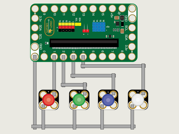
We'll use Maker Tape to connect the LEDs to the Bit Board on a LEGO baseplate.
-
Connect the Negative (-) sides of the LEDs to a Ground (GND) hole on the Bit Board.
-
Connect the Positive (+) side of the first LED to Pin 1 on the Bit Board.
-
Connect the Positive (+) side of the second LED to Pin 2 on the Bit Board.
-
Connect the Positive (+) side of the third LED to Pin 3 on the Bit Board.
-
Connect the Positive (+) side of the fourth LED to Pin 4 on the Bit Board.
-
You'll notice the Ground on the Bit Board (as well as the LED and other Crazy Circuits components we'll use) is color coded White.
-
-
-
If you've never used a micro:bit before you'll want to check out this guide: Bit Board V2 Setup and Use
-
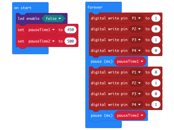
We're going to load the following code for our LED Blink Alternately program: https://makecode.microbit.org/_ih2Uu3bV2...
-
This code will make the first and third LEDs turn on while the second and fourth LEDs are off, then alternate.
-
We've created two variables, named pauseTime1 and pauseTime2 that allow us to set the length of time to pause in our code.
-
You'll notice we have a command for led enable set to false in the on start block.
-
The led enable command enables or disables the built-in LED matrix on the front of the micro:bit
-
We need to turn off the built-in LED matrix to properly use Pin 3 and Pin 4 otherwise they will be available to the built-in LED matrix and conflict with our code to control our LEDs.
-
You can see a description of the micro:bit pins here: https://makecode.microbit.org/device/pin...
-
-
-
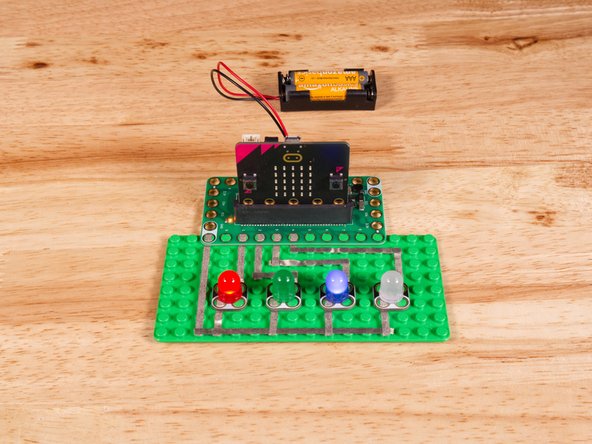
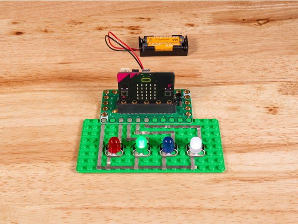
Once the code is loaded it should start running immediately.
-
You can power the micro:bit via the USB cable you used to load the code or you can use a battery pack plugged into the Bit Board.
-
LED one and three should turn on while two and four are off, then they will alternate so two and four are on and one and three are off.
-
In future guides we'll use four LEDs along with sensors or other input to act as a small bar graph or level indicator.
-
-
-
Follow along with our recorded Live Stream!
-
You can watch the full video of us walking through this project, along with explaining and exploring the code: https://www.youtube.com/watch?v=_ArsMH4A...
-
Attached Documents
