
Introduction
Connect four LEDs to a Bit Board and control them with a micro:bit
We'll make the LEDs turn on in order from one to four.
Video Overview
Featured Document
-
-
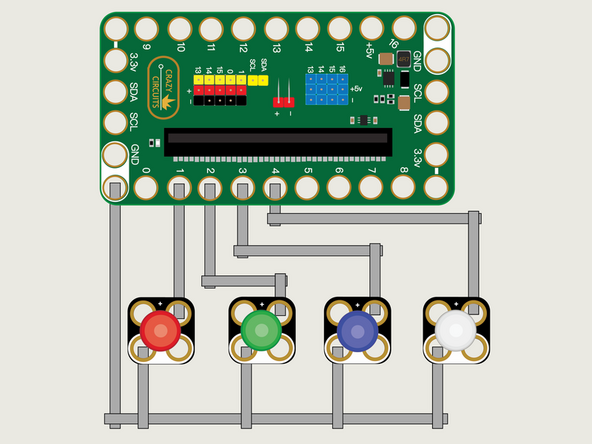
We'll use Maker Tape to connect the LEDs to the Bit Board on a LEGO baseplate.
-
Connect the Negative (-) sides of the LEDs to a Ground (GND) hole on the Bit Board.
-
Connect the Positive (+) side of the first LED to Pin 1 on the Bit Board.
-
Connect the Positive (+) side of the second LED to Pin 2 on the Bit Board.
-
Connect the Positive (+) side of the third LED to Pin 3 on the Bit Board.
-
Connect the Positive (+) side of the fourth LED to Pin 4 on the Bit Board.
-
You'll notice the Ground on the Bit Board (as well as the LED and other Crazy Circuits components we'll use) is color coded White.
-
-
-
If you've never used a micro:bit before you'll want to check out this guide: Bit Board V2 Setup and Use
-
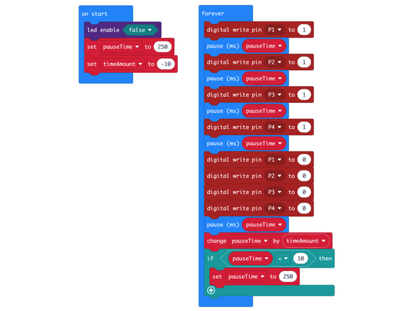
We're going to load the following code for our LED Blink Sequentially program: https://makecode.microbit.org/_F7zfHp5pU...
-
This code will turn on each LED in sequence and then turn them all off. For some extra fun we've added a change by function to decrease the pauseTime on each loop.
-
We've also added an if then block to check on the pauseTime and when it drops below 10 it will reset the value for pauseTime to 250.
-
You'll notice we have a command for led enable set to false in the on start block.
-
The led enable command enables or disables the built-in LED matrix on the front of the micro:bit
-
We need to turn off the built-in LED matrix to properly use Pin 3 and Pin 4 otherwise they will be used by the built-in LED matrix and conflict with our code to control our LEDs.
-
You can see a description of the micro:bit pins here: https://makecode.microbit.org/device/pin...
-
-
-
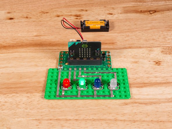
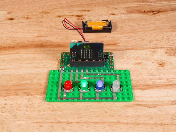
Once the code is loaded it should start running immediately.
-
You can power the micro:bit via the USB cable you used to load the code or you can use a battery pack plugged into the Bit Board.
-
Each LED (from one to four) should turn on, in sequence, and then all of them will turn off. We've also set it so the process will speed up on each loop and then rest when it gets too fast.
-
In future guides we'll use four LEDs along with sensors or other input to act as a small bar graph or level indicator.
-
-
-
Follow along with our recorded Live Stream!
-
You can watch the full video of us walking through this project, along with explaining and exploring the code: https://www.youtube.com/watch?v=_ArsMH4A...
-
Attached Documents
