
Introduction
Connect four LEDs to a Bit Board and control them with a micro:bit
We'll recreate the classic "Larson Scanner" using four LEDs.
Video Overview
Featured Document
-
-
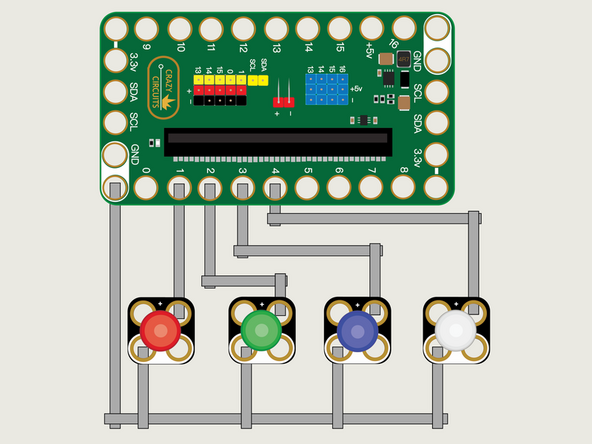
We'll use Maker Tape to connect the LEDs to the Bit Board on a LEGO baseplate.
-
Connect the Negative (-) sides of the LEDs to a Ground (GND) hole on the Bit Board.
-
Connect the Positive (+) side of the first LED to Pin 1 on the Bit Board.
-
Connect the Positive (+) side of the second LED to Pin 2 on the Bit Board.
-
Connect the Positive (+) side of the third LED to Pin 3 on the Bit Board.
-
Connect the Positive (+) side of the fourth LED to Pin 4 on the Bit Board.
-
You'll notice the Ground on the Bit Board (as well as the LED and other Crazy Circuits components we'll use) is color coded White.
-
-
-
If you've never used a micro:bit before you'll want to check out this guide: Bit Board V2 Setup and Use
-
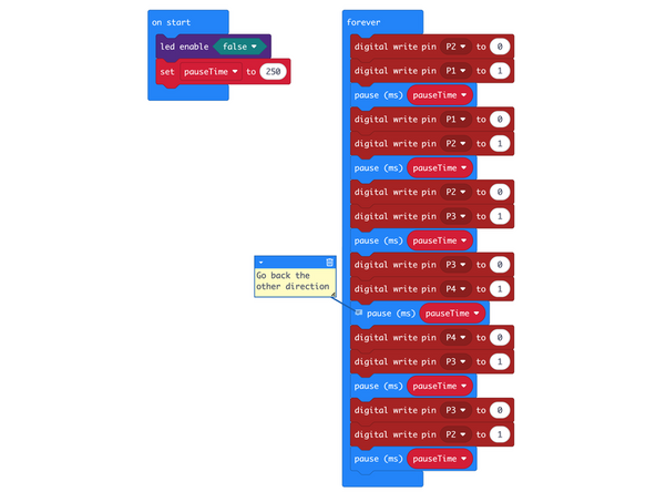
We're going to load the following code for our LED Larson Scanner program: https://makecode.microbit.org/_3qvTjUUjr...
-
This code will turn on an LED, then turn if off as it turns on the one next to it, and down the line to the end, and then go back in the other direction.
-
This code is pretty simple so we'll just call out two things. First the comment in the code. The little post-it note with some additional information. Comments can be very helpful in reminding you what a piece of code does.
-
Second, you'll notice the first line in the forever block turns off the LED on Pin 2. Isn't the pin already off when we start running our code? It is, but we need to account for when the loop comes back around, since the last thing the loop does it turn on the LED attached to Pin 2.
-
You'll notice we have a command for led enable set to false in the on start block. The led enable command enables or disables the built-in LED matrix on the front of the micro:bit
-
We need to turn off the built-in LED matrix to properly use Pin 3 and Pin 4 otherwise they will be used by the built-in LED matrix and conflict with our code to control our LEDs.
-
You can see a description of the micro:bit pins here: https://makecode.microbit.org/device/pin...
-
-
-
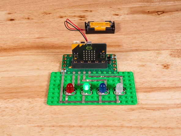
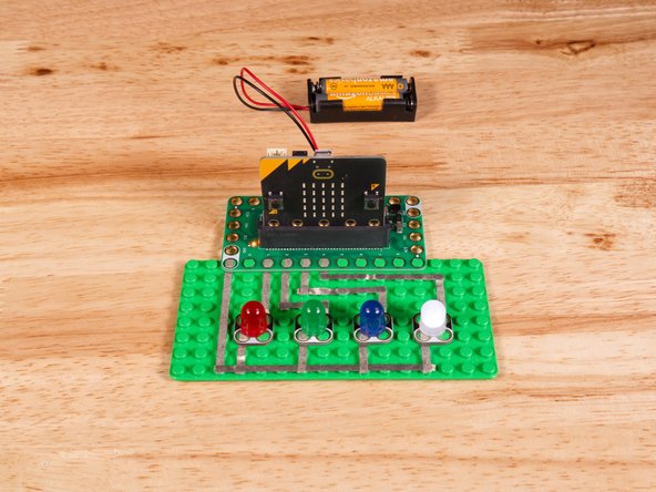
Once the code is loaded it should start running immediately.
-
You can power the micro:bit via the USB cable you used to load the code or you can use a battery pack plugged into the Bit Board.
-
This code looks fairly simple, and it is, though using just 4 LEDs and sequential pin numbering helps quite a bit.
-
In future guides we'll use four LEDs along with sensors or other input to act as a small bar graph or level indicator.
-
-
-
Follow along with our recorded Live Stream!
-
You can watch the full video of us walking through this project, along with explaining and exploring the code: https://www.youtube.com/watch?v=_ArsMH4A...
-
Attached Documents
