
Introduction
Connect a 7 Segment Display to a Bit Board and control it with code.
We'll explore code to control a 7 Segment Digital Display that can show numbers up to 9999.
Video Overview
Featured Document
-
-
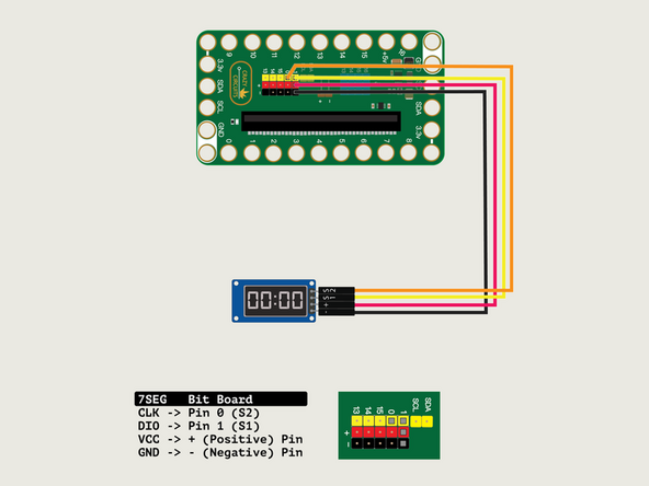
We'll connect the 7 Segment Display with a Crazy Circuits Ribbon Cable using all four wires.
-
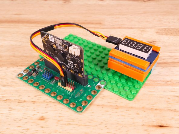
Start by plugging the connector with the three wires in it (Black, Red, Yellow) into the Pin 1 row of the Bit Board. (Make sure the Black wire is in - and the Yellow wire labeled S1 is closest to the number 1 on the Bit Board.)
-
We can then plug the Orange wire labeled S2 into Pin 0 on the Bit Board.
-
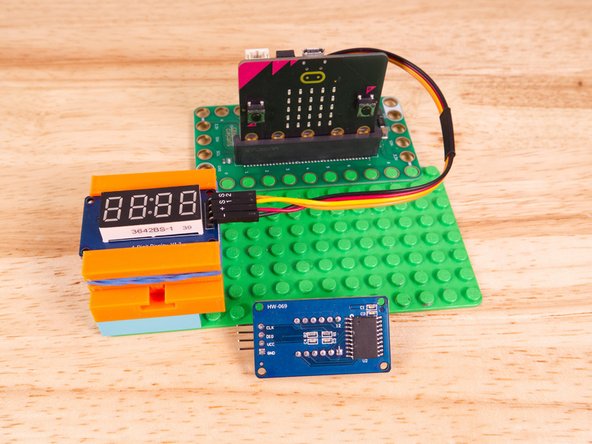
Now we'll connect the other end of the Ribbon Cable to the 7 Segment Display.
-
The pin labels are on the back of the 7 Segment Display PCB. From top to bottom it's CLK, DIO, VCC, GND.
-
CLK stands for Clock and DIO stands for Data Input/Output. VCC is the Positive (+) and GND is the Ground (-) or Negative.
-
S2 (Orange) goes to CLK, S1 (Yellow) goes to DIO, and then + (Positive) goes to VCC and - (Ground or Negative) goes to GND.
-
Make sure every wire is connected in the correct place, or our display will not work!
-
-
-
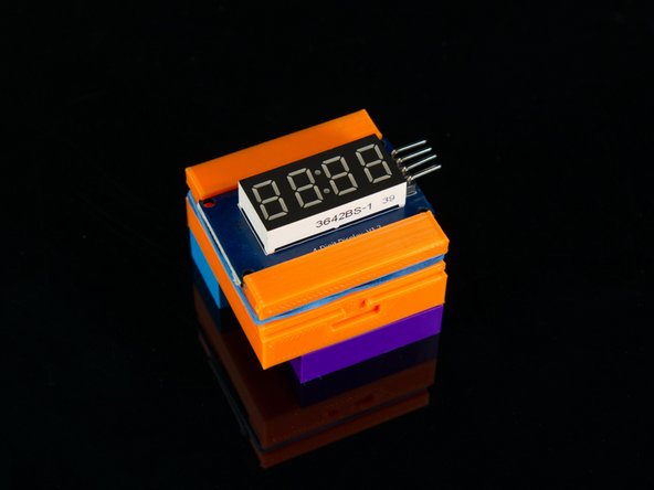
We used a 3D printed holder we designed to hold the 7 Segment Display in place on the LEGO baseplate.
-
You can find the guide for the holder here: 7 Segment Display Holder
-
Alternately you can use some LEGO bricks and a rubber band or tape to hold the display in place.
-
-
-
If you've never used a micro:bit before you'll want to check out this guide: Bit Board V2 Setup and Use
-
We're going to load the following code for our 7 Segment Intensity Functions program: https://makecode.microbit.org/_axc3xL6TP...
-
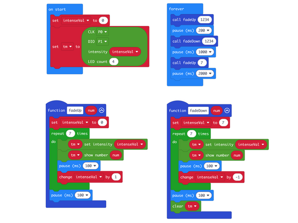
In the on start block we'll set up our display using the pins we've connected. CLK to Pin 0 and DIO to Pin 1.
-
For this example we've added two functions, fadeUp and fadeDown which will do what they suggest. One will fade up the brightness/intensity of the display while the other will fade it down.
-
We can call the function and pass in the parameter to see it fade up or down.
-
Note that while the intensity can go from 0 to 7 (8 levels) the 0 is still not the same as blank or "completely off" and it's really just the dimmest brightness setting.
-
Because of that we've added the clear statement at the end of the fadeDown function.
-
-
-
Once the code is loaded it should start running immediately.
-
You can power the micro:bit via the USB cable you used to load the code or you can use a battery pack plugged into the Bit Board.
-
The display will start blank and then slowly fade up the numbers 1234. It will then slowly fade down the numbers 1234.
-
Next the display will fade up the number 7 (technically 0007) until it reaches full brightness, and then blank the display and repeat the process.
-
-
-
Follow along with our recorded Live Stream!
-
You can watch the full video of us walking through this project, along with explaining and exploring the code: https://youtube.com/live/DI-rLHZK86g
-
Attached Documents
