
Introduction
Connect a 7 Segment Display and a Potentiometer to a Bit Board and control them with code.
We'll explore code to control a 7 Segment Digital Display that can show numbers up to 9999.
Video Overview
Featured Document
-
-
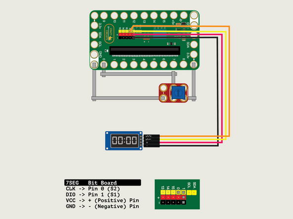
We'll connect the 7 Segment Display with a Crazy Circuits Ribbon Cable using all four wires.
-
Start by plugging the connector with the three wires in it (Black, Red, Yellow) into the Pin 1 row of the Bit Board. (Make sure the Black wire is in - and the Yellow wire labeled S1 is closest to the number 1 on the Bit Board.) We can then plug the Orange wire labeled S2 into Pin 0 on the Bit Board.
-
Now we'll connect the other end of the Ribbon Cable to the 7 Segment Display. The pin labels are on the back of the 7 Segment Display PCB. From top to bottom it's CLK, DIO, VCC, GND.
-
CLK stands for Clock and DIO stands for Data Input/Output. VCC is the Positive (+) and GND is the Ground (-) or Negative.
-
S2 (Orange) goes to CLK, S1 (Yellow) goes to DIO, and then + (Positive) goes to VCC and - (Ground or Negative) goes to GND.
-
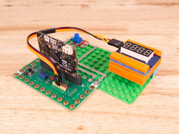
We'll need to connect one side of the Potentiometer to Ground (GND) and the other side to 3.3v
-
We will then connect the center of the Potentiometer to Pin 0. (Note that Pin 0 is an analog pin, which we'll need for the Potentiometer.)
-
-
-
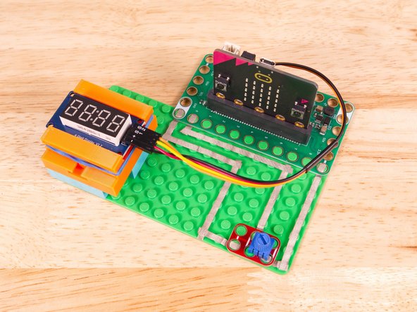
We used a 3D printed holder we designed to hold the 7 Segment Display in place on the LEGO baseplate.
-
You can find the guide for the holder here: 7 Segment Display Holder
-
Alternately you can use some LEGO bricks and a rubber band or tape to hold the display in place.
-
-
-
If you've never used a micro:bit before you'll want to check out this guide: Bit Board V2 Setup and Use
-
We're going to load the following code for our 7 Segment Display Potentiometer Map More program: https://makecode.microbit.org/_WX740aA98...
-
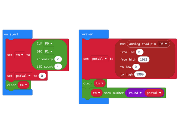
In the on start block we'll set up our display using the pins we've connected. CLK to Pin 0 and DIO to Pin 1.
-
We'll also create a variable named potVal to hold the value we read from the analog pin that is connected to the Potentiometer.
-
In the forever block the map function allows us to take the input and map it onto a different scale. This time we'll map 0 to 1023 onto 0 to 9999.
-
We will also use the round function to make sure we get an integer and not a floating point (or decimal) value.
-
-
-
Once the code is loaded it should start running immediately but won't display anything until we turn the dial.
-
You can power the micro:bit via the USB cable you used to load the code or you can use a battery pack plugged into the Bit Board.
-
Turn the Potentiometer dial and you should see the number on the 7 Segment Display change.
-
While the 7 Segment Display is capable of displaying a value between 0 and 9999 our analog pin can only create values between 0 and 1023.
-
So what will happen when we turn the dial? What is the lowest and highest number we might see?
-
We are also dealing with the issue of trying to map a smaller scale onto a larger scale so the values will always jump by large increments.
-
You will probably also see the display flicker a bit, since even the tiniest variance in our input will be magnified on the output.
-
All in all, this is an interesting exercise, but may not have as many real-world use cases as the previous guide.
-
-
-
Follow along with our recorded Live Stream!
-
You can watch the full video of us walking through this project, along with explaining and exploring the code: https://www.youtube.com/live/X6iQJrTScCM
-

Attached Documents
