
Introduction
Connect a Thumbstick to a Bit Board and control the built-in LED Matrix on the micro:bit.

Video Overview
Featured Document
-
-
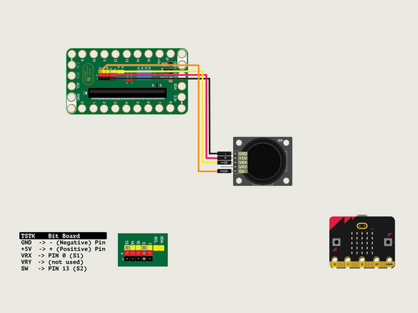
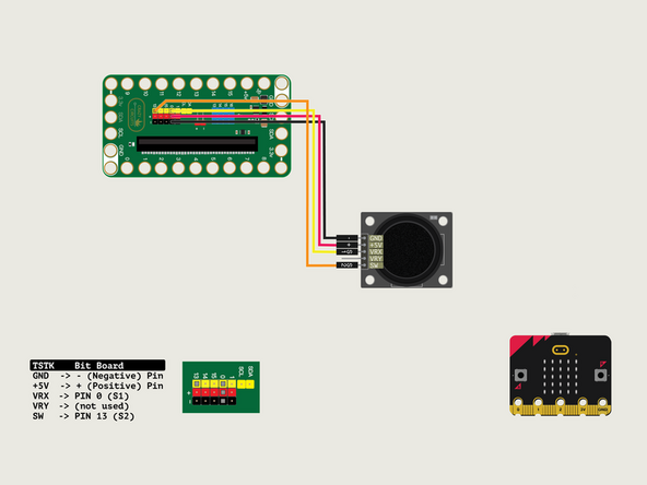
We'll connect the Thumbstick with a Crazy Circuits Ribbon Cable using all four wires.
-
Plug the three-wire connector of the Crazy Circuits Ribbon Cable into the row with Pin 0 on the Bit Board. The wire colors should match the pin header colors, with S1 (yellow) going to the yellow pin.
-
Next, plug S2 (orange) into Pin 13. (S2 is separated from the three-wire connector to allow you to plug it into another row.)
-
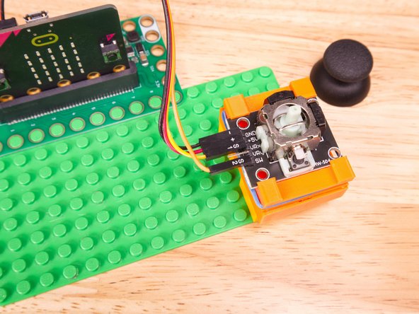
To the Thumbstick plug - (black) into GND, + (red) into +5V; S1 (yellow) into VRx; S2 (orange) into SW.
-
We won't plug anything into VRy pin for this example.
-
-
-
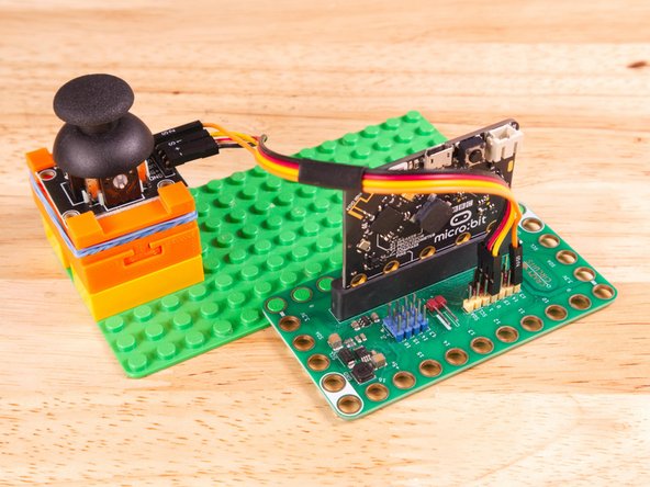
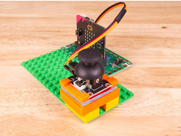
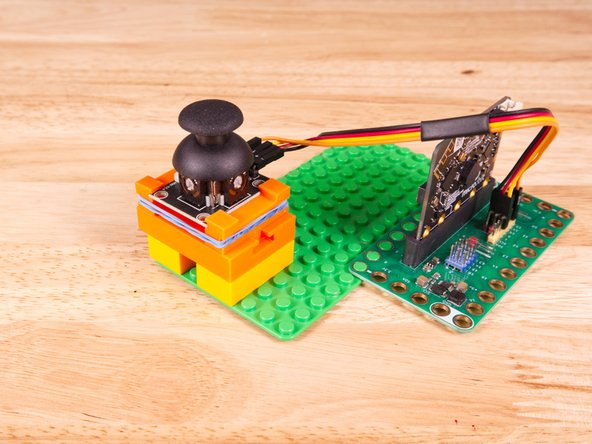
We used a 3D printed part we designed to hold the Thumbstick in place on a LEGO baseplate.
-
We attached two 2x4 LEGO Bricks to the bottom of the 3D printed holder to allow it to snap onto the LEGO Baseplate a bit easier.
-
Alternately you can try to use some LEGO bricks and some rubber bands to hold the sensor in place, or just hold it in your hand.
-
3D print your own Thumbstick Sensor Holder.
-
-
-
If you've never used a micro:bit before you'll want to check out this guide: Bit Board V2 Setup and Use
-
We're going to load the following code for our Thumbstick LED Matrix Simple program: https://makecode.microbit.org/_R3dbyTHb8...
-
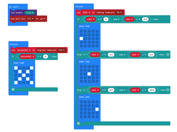
In the on start block we'll enable the LED matrix and set Pin 13 to pull up.
-
In one forever loop we'll set buttonVal to read Pin 13 (which is connected to the button/switch on the Thumbstick) and if it's pressed we'll show an 'X' on the LED Matrix.
-
In the other forever loop we'll set xVal to the value from Pin 0 (which is connected to VRx, the X-axis of the Thumbstick) and then check if the value is between a number of ranges.
-
Remember, an analog input can give us values from 0 to 1023. Here we've divided that range into three sets, and show a corresponding pixel based on the Thumbstick position.
-
-
-
Once the code is loaded it should start running immediately.
-
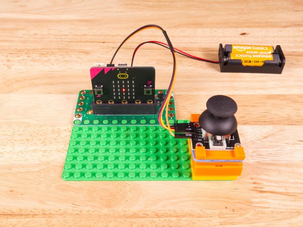
You can power the micro:bit via the USB cable you used to load the code or you can use a battery pack plugged into the Bit Board.
-
Move the Thumbstick left and right and you should see a pixel on the display move left and right. Press the Thumbstick down to see an 'X' on the screen.
-
-
-
Follow along with our recorded Live Stream!
-
You can watch the full video of us walking through this project, along with explaining and exploring the code: https://www.youtube.com/live/itzcDaRWh9Q
-
Attached Documents
