
Introduction
Program the built-in LED Matrix found on the micro:bit
We'll explore how we can control the LED Matrix to show information and animations.
Video Overview
Featured Document
-
-
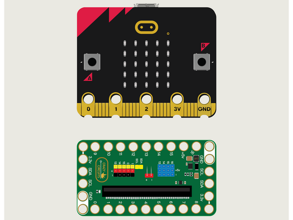
For this guide we won't need Maker Tape or any components. We're just going to put the micro:bit into the Bit Board.
-
We're only going to connect a USB cable and use the built-in LED Matrix found on the front of the micro:bit
-
-
-
If you've never used a micro:bit before you'll want to check out this guide: Bit Board V2 Setup and Use
-
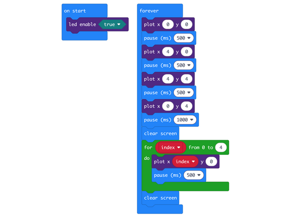
We're going to load the following code for our LED Matrix Plotting program: https://makecode.microbit.org/_5YU3tbXbV...
-
We're going to plot points in the X/Y grid of pixels. First in each of the four corners, and then using a loop to plot points across the first row.
-
Note that while the matrix is 5x5 they are numbered 0 through 4 in the X and Y axes.
-
So the first LED on the left is 0 and the LED all the way on the right is 4. (These are on the X axis.)
-
Likewise the top row of LEDs is 0 on the Y axis and the bottom row is 4.
-
-
-
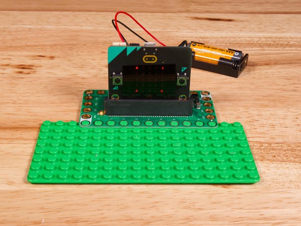
Once the code is loaded it should start running immediately.
-
You can power the micro:bit via the USB cable you used to load the code or you can use a battery pack plugged into the Bit Board.
-
The micro:bit's built-in LED Matrix will turn on an LED in each corner, then clear the screen, and then turn on LEDs on the top row, from left to right, and then clear the screen.
-
-
-
Follow along with our recorded Live Stream!
-
You can watch the full video of us walking through this project, along with explaining and exploring the code: https://youtube.com/live/3A9rYMbcC04
-

Attached Documents
