Introduction
Conductive paint is extremely fun to use in place of a Potentiometer (variable resistor) in projects and you can use it to control all sorts of things. In this activity we'll be using Bare Conductive Paint to control the sound being produced by a Piezo Speaker hooked up to one of our Invention Boards.
If you have a Robotics Board you can also do this project, you'll just have to change a couple of pin numbers in the code.
Video Overview
Featured Document
-
-
Grab a Resistor and screw it into the Screw Terminal Chip.
-
We're using a 460 ohm resistor, however a resistor of near or similar value will work.
-
If you don't have a Screw Terminal Chip around you can always just use Conductive Tape to hold the Resistor down. We attached a small diagram of what that would look like at the end of this guide.
-
-
-
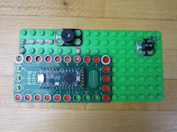
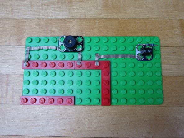
The Invention Board won't lay flat onto our 8x16 base plate, so we'll need to make a platform for it. We're using several thin plates to create the platform.
-
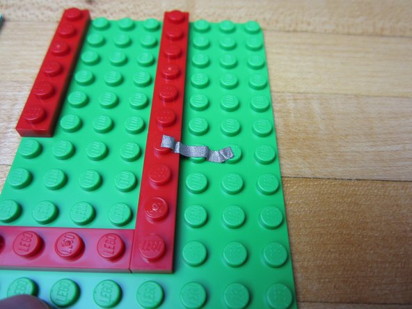
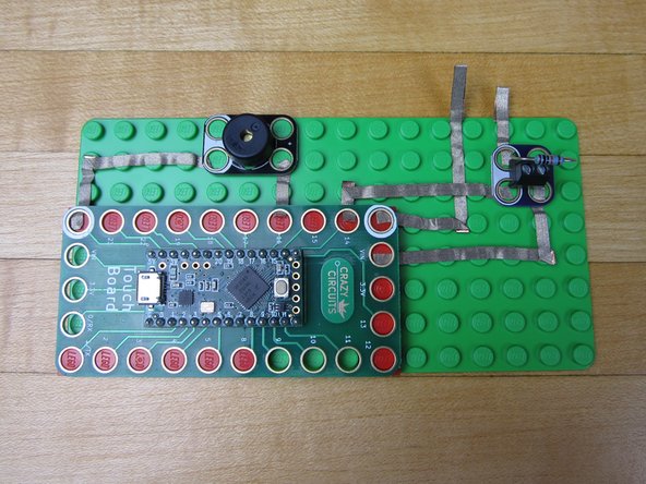
You NEED to have bricks below the pins that you're using, otherwise the tape won't make a connection. We're using both Grounds, Pins 14 and 16, and the VIN on the right side.
-
-
-
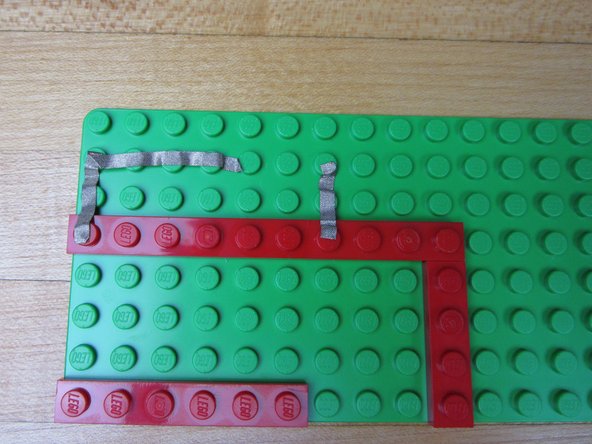
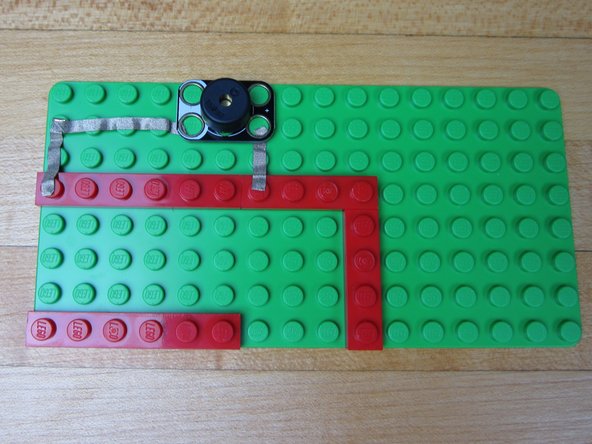
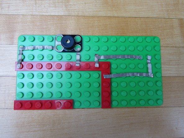
Run Maker Tape from Pin 16 to where you want your Piezo Speaker. Cut excess tape and press down with your fingernail or the Piezo Speaker.
-
Run Maker Tape from the left side Ground Pin (white circle) to the Piezo Speaker.
-
Press your Piezo Speaker into place.
-
-
-
Place your Screw Terminal near the top right corner for placement.
-
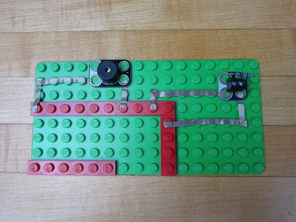
Run a line of Maker Tape from Pin 14 to the white side of the Screw terminal.
-
Cut excess tape and press to fit.
-
-
-
Run a line of Maker Tape from the VIN pin to the blue side of the Screw Terminal.
-
Cut excess tape and press to fit.
-
-
-
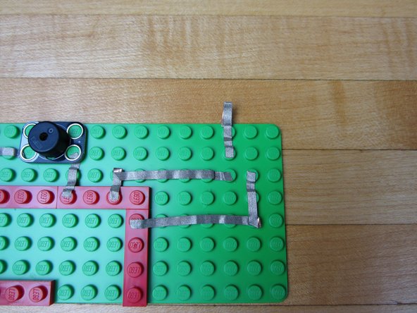
Use a piece of Maker Tape and and go from the second hole on the Screw Terminal off the side of your building surface.
-
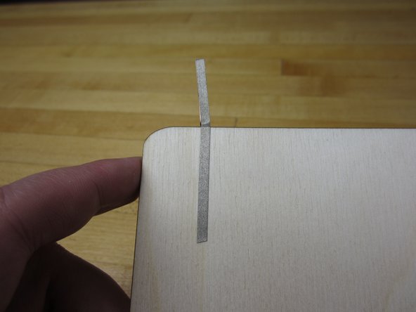
Fold over the tape onto itself so it's conductive on both sides. You can also just run it to the bottom side of the base plate as well.
-
-
-
Use a longer line of tape and go from the Ground pin off the side of the board.
-
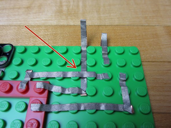
Start by threading a long piece of tape UNDER the pin 14 line of tape.
-
Connect one end to the Ground pin. Let the other end hang off the edge, and fold it over like you did before.
-
Use a pencil, screwdriver, or paper clip to push down the tape so that the Ground line isn't touching the Pin 14 line.
-
-
-
If you've never used your Invention Board before, review the Invention Board User Guide.
-
Plug your Invention Board into your computer and open up the Arduino Software.
-
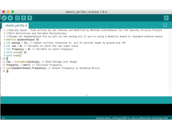
Follow this link and choose either the ConstantTone or StepTone code. Copy and paste the code into a new project window in the Arduino Software.
-
Upload the Code.
-
-
-
If you're using a Robotics board you'll need to change a couple of lines.
-
Change the Speaker Output Pin to 3.
-
Change the Input (Analog Input) to A5.
-
At the end of this guide is a diagram for how we suggest you hook up your Robotics Board, however the pins you use are entirely up to you.
-
-
-
Leave your Invention Board plugged into your computer.
-
Use an Alligator Clip to connect your two Alligator Connection Points together.
-
No matter which code you're using, you should hear something come out of your speaker.
-
-
-
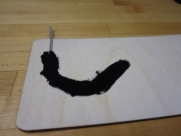
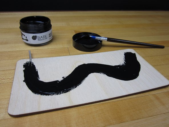
We're using a piece of wood for our paint surface, but a piece of cardboard or paper would work just fine.
-
Take a long piece of tape and apply it to your work area. Fold it over and have it connect to the back side if your board.
-
Starting on top of your tape, apply a long line of paint. Try to paint on evenly.
-
Bare Conductive Paint is water soluble, meaning it more or less melts when it touches water. Use some clear spray paint to seal your project.
-
-
-
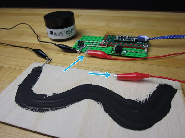
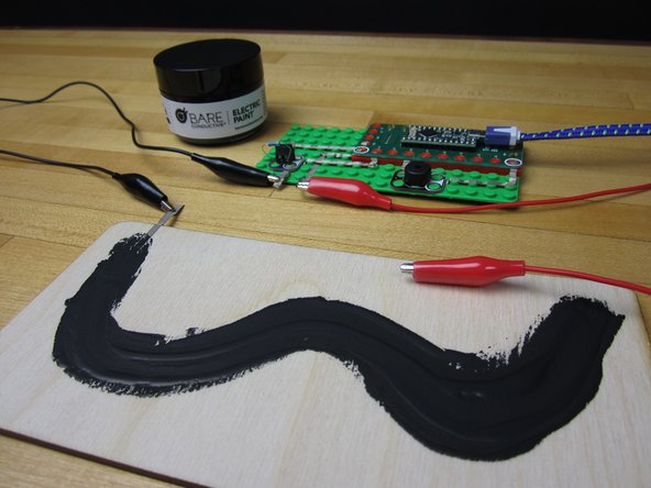
Use an Alligator Clip to connect your electronics to the tape on your painting surface.
-
Use your second Alligator Clip and connect it to the second output from your electronics.
-
Use the second Alligator Clip as a probe. Move it around your paint area to change the types of sound your project is making.
-
-
-
The #1 problem people have with this project is that they had issues uploading the code.
-
A longer line of paint is much more useful than a short line of paint.
-
We used a 460 ohm resistor, however you can use one with a higher value if you want. Test to see what happens when you use a higher value resistor.
-
When in doubt, use the "sequential tone" code. The "constant" tone can be a bit annoying.
-
You can use this EXACT same process with ANY Arduino project that uses a variable resistor. Controlling a servo or LED is really simple using this process.
-


