
Introduction
Stop using weak, organic, pumpkins for your Halloween decorations! Instead create a cold, robotic pumpkin that will never let you down.
This project creates a simple Larson Scanner out of four LEDs. The Larson Scanner effect was seen in such classic TV shows as Battlestar Galactica and Knight Rider. Since we don't have a talking car we're putting our scanner into a pumpkin body made out of LEGO.
Video Overview
Featured Document
-
-
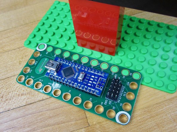
Use an 8x16 sized base plate as your build platform.
-
We used a wide variety of orange and black pieces.
-
The most important are some 1x2 or 1x4 sized clear bricks for the "eyes."
-
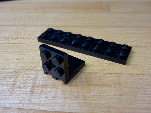
The second most important brick is a right angle brick, so we can stick our LEDs on vertically.
-
If you need to buy specific bricks in specific colors, try BrickLink or BrickOwl.
-
-
-
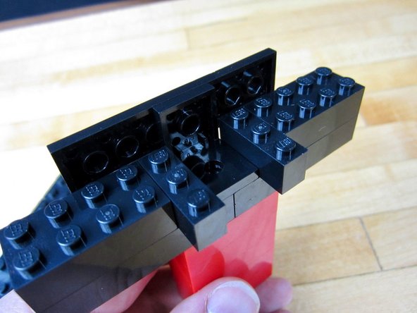
Build your Pumpkin.
-
Notice how we use 2 wide bricks on the bottom half, and 1 wide bricks on the upper half.
-
-
-
Use a right angle LEGO piece and a 2x8 plate to create the LED holder.
-
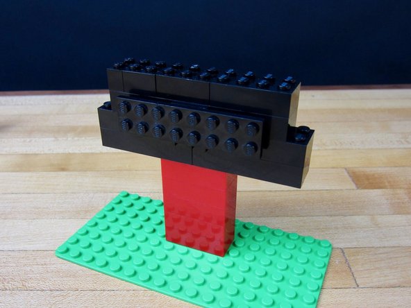
Use standard bricks to build the tower that holds everything.
-
-
-
Stick your tower to the base plate.
-
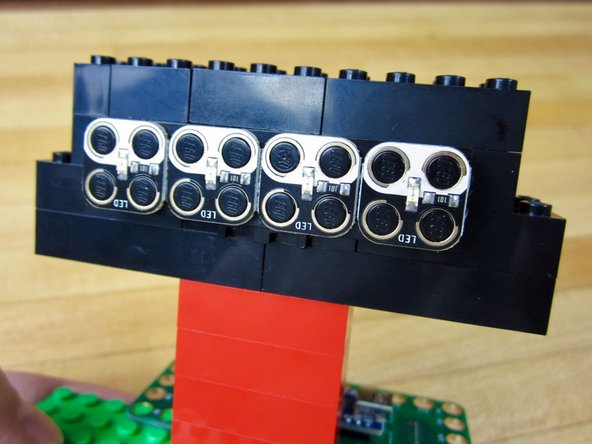
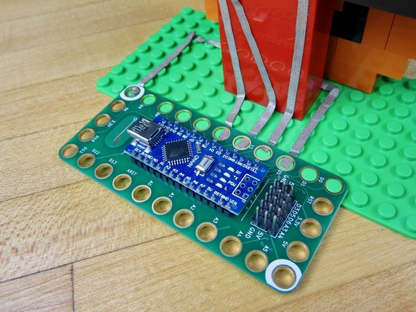
Stick on the LEDs and Robotics Board.
-
-
-
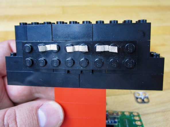
Connect the Grounds between each of the LEDs.
-
-
-
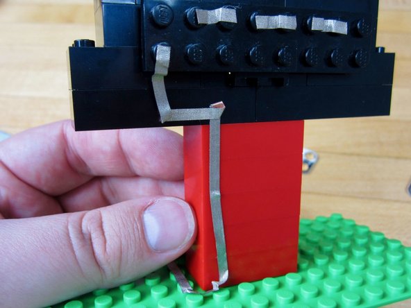
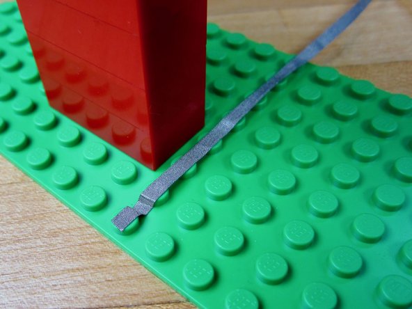
Run a long line of tape from the far left LED to Pin 2 on the Robotics Board.
-
-
-
Run a line of tape from the 2nd LED back around the LED holder.
-
Connect to Pin 3 on the Robotics Board.
-
-
-
Do the same thing with the 3rd and 4th LEDs.
-
They connect to Pins 4 and 5 on the Robotics Board.
-
-
-
Run a long line of tape from your 4th LED to the Ground hole on your Robotics Board.
-
Put on the LEDs when finished.
-
-
-
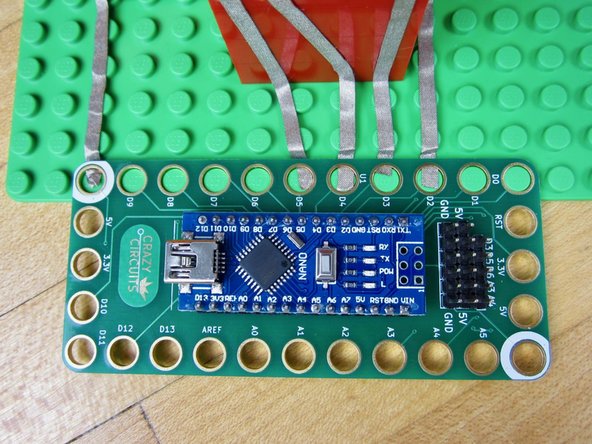
Pop on the Robotics Board.
-
Double check your connections to make sure you're using Pin 2-5, and that you're also hooked up to Ground.
-
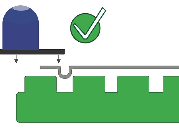
If your board isn't popping on check to make sure your tape ends are not too long.
-
-
-
If you've never used our Robotics board before, STOP! Read the Robotics Board User Guide. You'll need it to download all the right software and drivers.
-
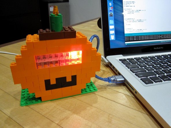
Open up the Arduino software and open up a new project window. Copy and Paste this code into the project window.
-
Upload the code.
-
You can add more LEDs to your project by changing just a couple of lines of code. On line 2 you can change the number of LEDs you're using. Then on line 6 add the other LED Pins that you're using.
-
-
-
Once the code is uploaded it will run every time it is powered on.
-
Use a USB wall adaptor to power it independently from a computer.
-
You can use a 4 AA or AAA battery holder and attach it to the 5V and Ground on the board. This can be done with the help of a Screw Terminal chip.
-


Attached Documents
