Introduction
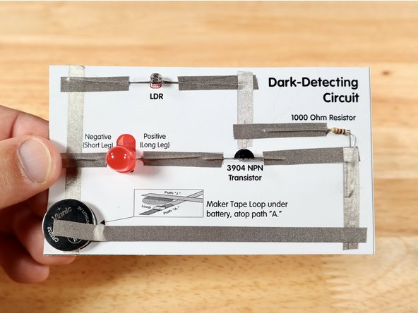
Using a resistor, a coin-cell battery, a transistor and a light-dependent-resistor, create a light circuit that turns on as it gets dark!
Featured Document
-
-
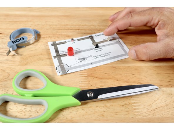
Before assembly of the circuit, each component will need to be prepared for placement where shown on the template.
-
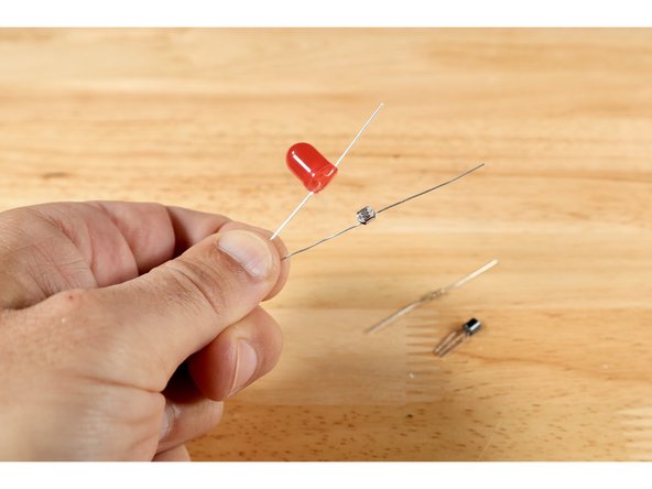
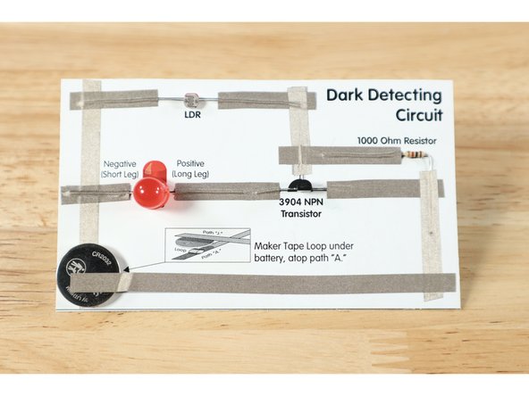
The two legs of both the LED and the LDR should be folded outward in opposite directions, allowing them to lay flat in the places pictured on the template. The legs of the LDR are both the same length and it can be placed on the diagram in any orientation. The LED legs, however, are different lengths and the orientation needs to match the diagram.
-
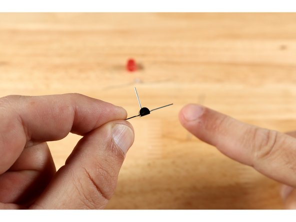
Using the flat side of the 3 legged transistor as a guide for orientation, bend the three legs outward away from the center of the part as shown on the template. This should allow for the part to be placed as shown with the flat side of the black part facing the bottom of the template; two legs extending outward and the middle one extending upward.
-
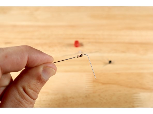
Only one leg of the striped resistor needs to be bent and it does NOT matter which one it is. Choose one and bend it at a 90 degree angle to match the template.
-
-
-
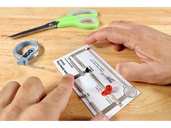
Measure, cut, peel, and stick Maker Tape paths A-F where shown on the diagram. These Maker Tape paths are all placed on TOP of component legs. In this order, all components should now be lightly held in place.
-
Measure, cut, peel, and stick paths G, H, and I where shown on the template. Again, all these pathways are placed on TOP of the component legs.
-
-
-
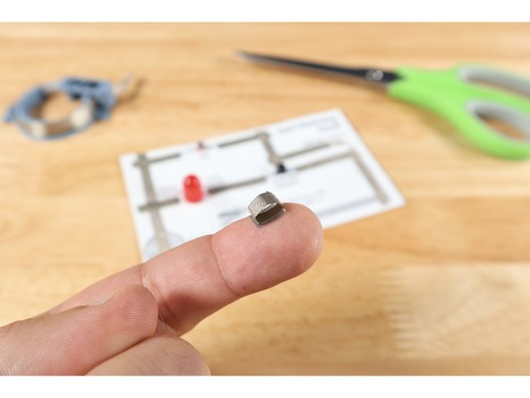
Cut a small 3/4" piece of Maker Tape and roll it into a sticky-side-out tape loop. Stick this loop atop the battery end of Tape Path A as shown in the tape loop diagram on your template.
-
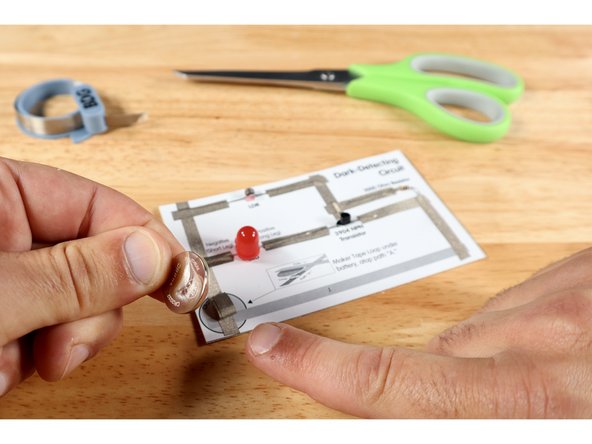
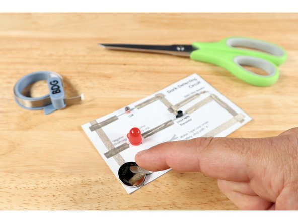
Stick the battery atop the tape loop with the Positive (+) Side facing UP.
-
Measure, cut, peel, and stick Maker Tape path J. This path should cross over the end of path I, extend left and be stuck to the top of the battery. Your circuit is now complete!
-
-
-
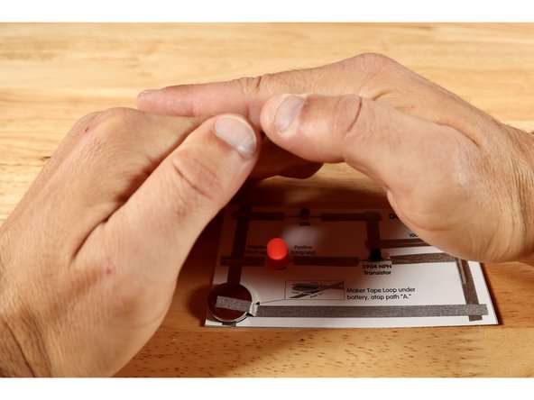
If you have assembled your circuit in the light, the LED should NOT be lit. When you cover the LDR or even cast a shadow over it, the LED should turn on.
-
The general idea behind this circuit begins with understanding how an LDR works. It’s still basically a resistor; so it’s designed to slow current flow through it. However, the amount that it does this depends on the amount of light around it. More light = Less resistance/ Less light (dark) = More resistance.
-
Circuits that use LDRs often have multiple pathways near the outcome; one that passes THROUGH the outcome component and one that goes around it.
-
Adjusting the resistance at the LDR forces the electricity to travel different paths under different conditions.
-
One path bypasses the LED while the other goes through it.
-
Found often in solar garden lights that only turn on when it gets dark, this circuit is surprisingly simple. Now, you've made one yourself! Hooray!
Found often in solar garden lights that only turn on when it gets dark, this circuit is surprisingly simple. Now, you've made one yourself! Hooray!