
Introduction
Note: This is a project that predates our Rover Tank. This is a complex project requiring many components. We recommend you look at the simplified Rover Tank Body guide instead.
This gripper was built to work with our LEGO Tank (Prototype).
Parts
- Brick Compatible 360 Degree Servo
- LEGO Technic Beam 3 x 3.8 x 7 Beam Bent 45 Double (32009 / 41486) × 2
- LEGO Beam 11 (32525 / 64290) × 3
- LEGO Beam 3 x 3 T-Shaped (60484)
- LEGO Beam 5 x 0.5 with Axle Holes on each end (11478 / 44864) × 2
- LEGO Axle 6 (3706) × 2
- LEGO Axle 4 with End Stop (87083) × 6
- LEGO Axle 4 (3705)
- LEGO Axle Connector (Smooth with ‘x’ Hole) (59443)
- LEGO Bushing (6590 / 42798)
- LEGO Cross Block Beam Bent 90 Degrees with 4 Pins (49130 / 55615) × 2
- LEGO Cross Block 90° 1 x 2 (Axle/Pin) (6536 / 40146) × 2
- LEGO Cross Block 2 x 2 Split (Axle / Twin Pin) (41678) × 4
- LEGO Technic Through Axle Connector with Bushing (32039 / 42135)
- LEGO Long Pin with Friction (6558 / 42924) × 4
- LEGO Axle to Pin Connector (3749 / 6562)
- LEGO Gear with 24 Teeth (3648 / 24505) × 2
- LEGO Worm Gear with New Axle (32905)
Video Overview
-
-
If you built our LEGO Tank (Prototype) and then upgraded it by adding the LEGO Tank Remote Control (Prototype) adding this Gripper is the next step!
-
The "thing" at the end of a robot arm is known as an end effector, and it is designed to interact with the environment.
-
There are a variety of designs for two finger "grippers" and they tend to share certain features.
-
For our Gripper we're going to build it using nothing but LEGO parts! We've specified all parts and provided links if you want to build your own.
-
If you've got a 3D printer check out the guide we have for a LEGO Gripper (with 3D Printed Parts) It's a more minimal build compared to this one.
-
-
-
We're going to use a Crazy Circuits Bit Board along with a micro:bit and a LEGO Compatible 360 Degree Servo. (We'll power it all with a 2 AAA Battery Pack.)
-
If you're adding the Gripper to your LEGO Tank (Prototype) you'll already have a Bit Board, micro:bit, and battery pack on the tank, so all you need is one more servo.
-
The electronics portion of this project will be very easy since we just need to plug the servo into the Bit Board. We'll also be loading some code, but we'll provide that for you!
-
-
-
Gather all of the LEGO parts needed to build the Gripper.
-
If you don't have these exact parts you can often make substitutions. For instance, if you have beams that are longer than those specified they'll work, but you may need to change where things are connected.
-
LEGO is about building what you want to build! Consider our guide a suggestion for your own build which should be based on the parts you have available.
-
-
-
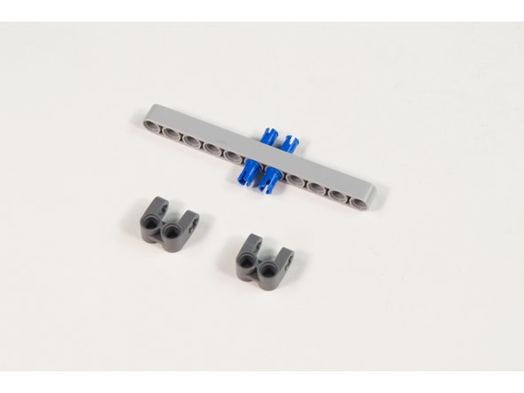
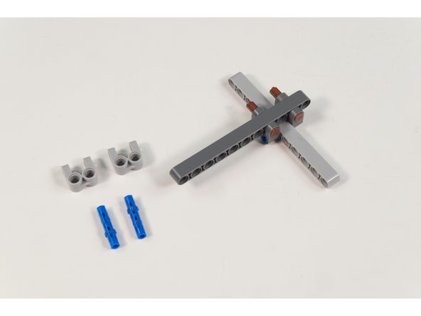
We’ll start by adding support blocks so we can attach two of the beams.
-
Place 2 LEGO Long Pin with Friction into LEGO Beam 11 as shown.
-
Add 2 LEGO Cross Block 2 x 2 Split (Axle / Twin Pin) as shown.
-
If you don’t have the correct pins you can try to use axles and bushings to hold things in place. Usually there’s a LEGO alternative that will work.
-
-
-
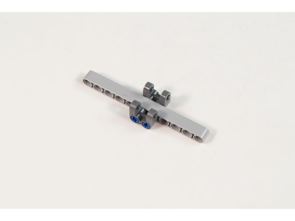
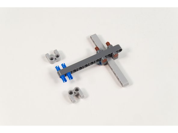
Two axles will be used to hold the beams together.
-
Place LEGO Beam 11 between Cross Block 2 x 2 Split (Axle / Twin Pin) and hold in place with 2 LEGO Axle 4 with End Stop.
-
Here’s another place where you could use bushings and longer axles if needed. We try to suggest the best part for the job, but as always, use what you have available.
-
-
-
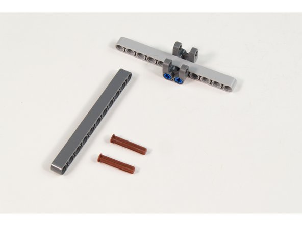
Place 2 LEGO Long Pin with Friction into LEGO Beam 11 (32525 / 64290) as shown.
-
Add 2 LEGO Cross Block 2 x 2 Split (Axle / Twin Pin) as shown.
-
-
-
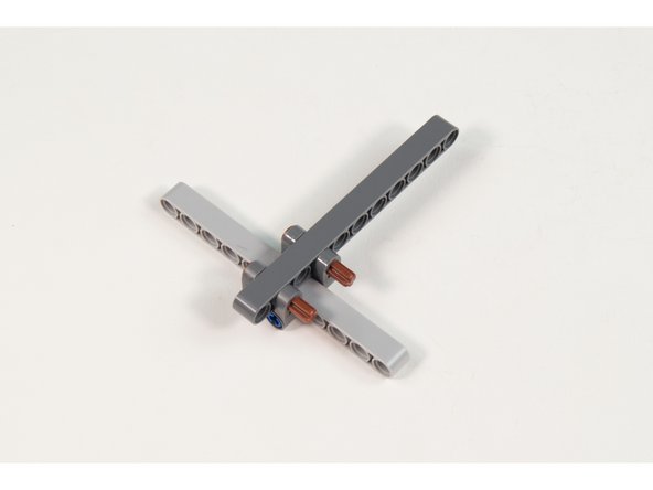
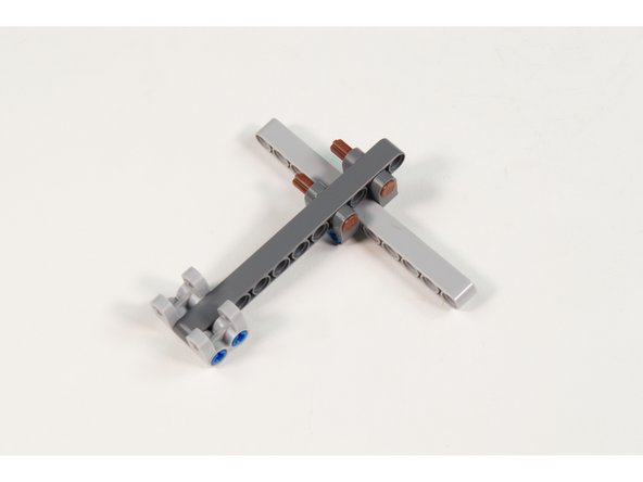
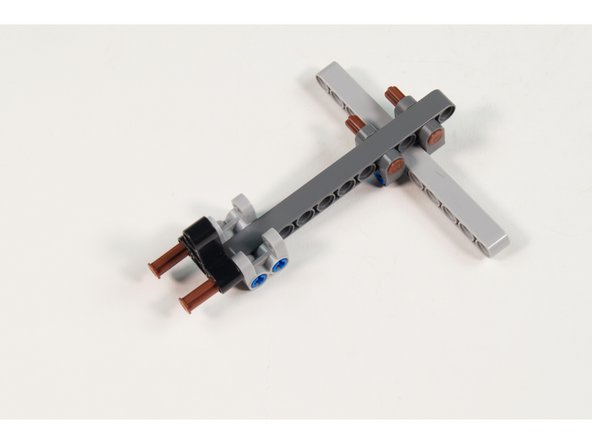
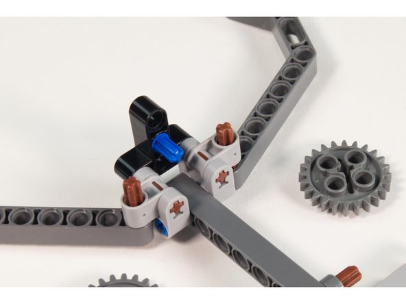
Place 2 LEGO Axle 4 with End Stop halfway through LEGO Beam 3 x 3 T-Shaped as shown.
-
Make sure the axles are only part way through so we can add more parts in the next step!
-
-
-
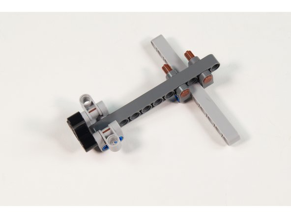
Add 2 LEGO Cross Block 90° 1 x 2 (Axle/Pin) by pushing the 2 LEGO Axle 4 with End Stop parts into place.
-
-
-
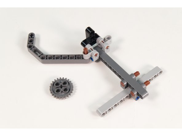
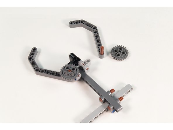
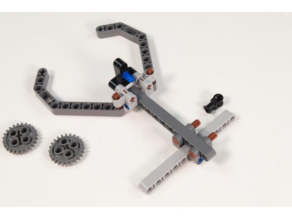
Each “Finger” will consist of an angled beam, a gear, and an axle.
-
Press a LEGO Axle 4 with End Stop into the last hole on a LEGO Technic Beam 3 x 3.8 x 7 Beam Bent 45 Double as shown.
-
Slide the axle up through the hole in the LEGO Technic Beam 3 x 3.8 x 7 Beam Bent 45 Double.
-
Press the Gear with 24 Teeth onto the axle.
-
-
-
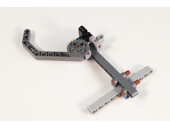
Repeat Step 9 with the other finger.
-
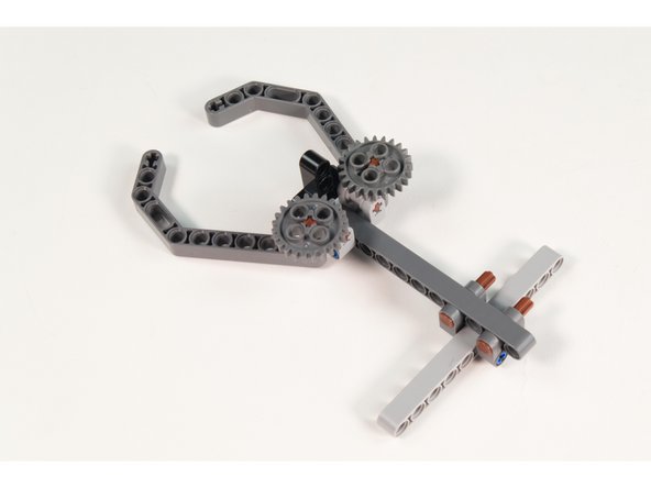
You should now have both fingers in place, and they will pivot freely.
-
Once we add the servo and worm gear they won’t move freely as the servo and worm gear will provide the movement.
-
-
-
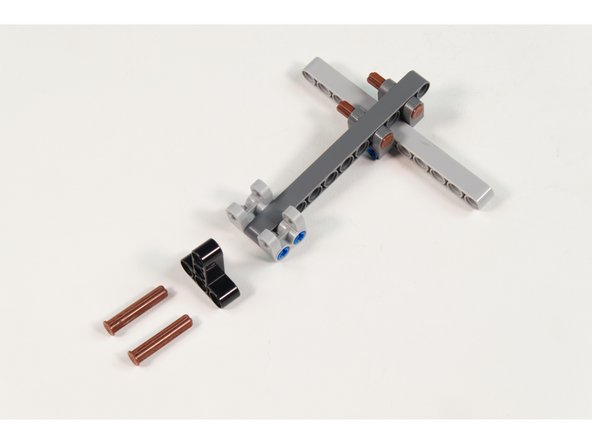
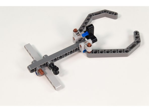
Press the Axle to Pin Connector into the LEGO Beam 3 x 3 T-Shaped into the center hole as shown.
-
You will need to remove the gears to add the pin. Leave them off until Step 15.
-
The “Pin” half goes into the LEGO Beam, and the “Axle” half should be sticking out.
-
-
-
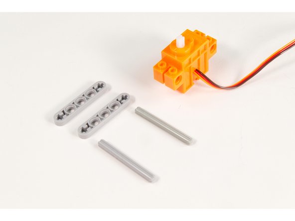
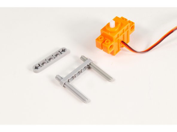
Let’s prepare our servo to fit into place.
-
Press 2 LEGO Axle 6 parts through the ends of a LEGO Beam 5 x 0.5 with Axle Holes as shown.
-
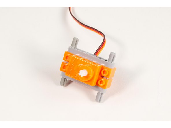
Slide the servo in place onto the axles.
-
Press the second LEGO Beam 5 x 0.5 with Axle Holes onto the other end of the axles.
-
Make sure the servo wire is on the top.
-
Later we'll adjust the axles so that more of the axles are sticking out on the bottom than the top.
-
-
-
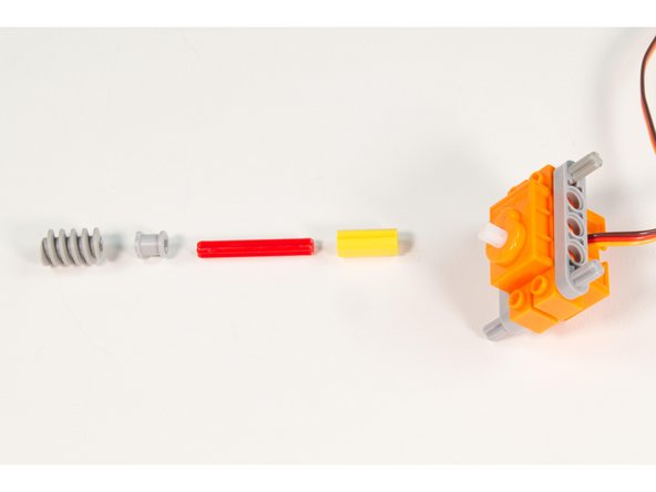
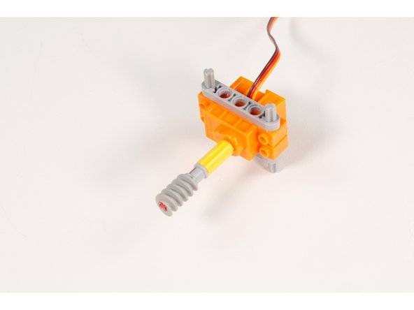
Press the LEGO Axle Connector (Smooth with ‘x’ Hole) onto the servo shaft.
-
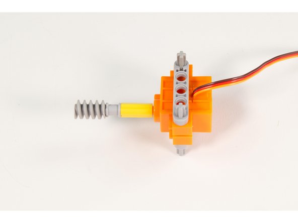
Press the LEGO Axle 4 into place, then add the LEGO Bushing and finally the LEGO Worm Gear with New Axle.
-
Press them all the way down the shaft. We’ll adjust them later, but need them all the way down to start.
-
If you have the LEGO Worm Gear with Old Axle (4716) it's a perfect alternative to the LEGO Worm Gear with New Axle.
-
-
-
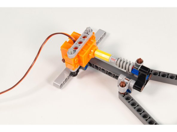
Press the LEGO Technic Through Axle Connector with Bushing onto the frontmost LEGO Axle 4 with End Stop on the back of the main assembly with the axle hole oriented upwards.
-
If you did not remove the gears in Step 11 do that now.
-
-
-
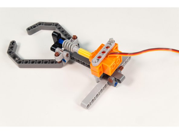
The servo can now be put in place.
-
Slide the servo into place so one of the axles goes into the LEGO Technic Through Axle Connector with Bushing.
-
-
-
With the servo in place you can now slide the LEGO Worm Gear with New Axle forward along with the LEGO Bushing to hold it in place.
-
You may need to rotate the shaft to get it to line up with the axle end of the pin. Just grab the axle connector and spin it until the axle is aligned.
-
-
-
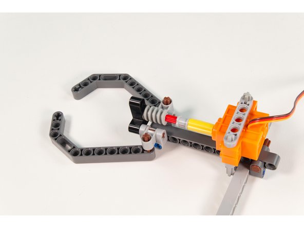
We can now add the gears back in place.
-
Since we want the fingers aligned with each other the easiest way to do that is to position them open to 90 degree angles.
-
-
-
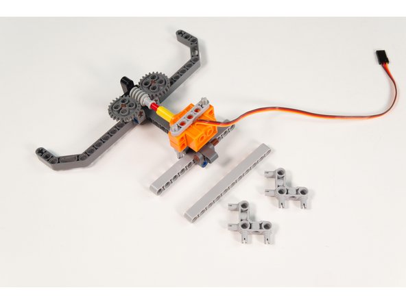
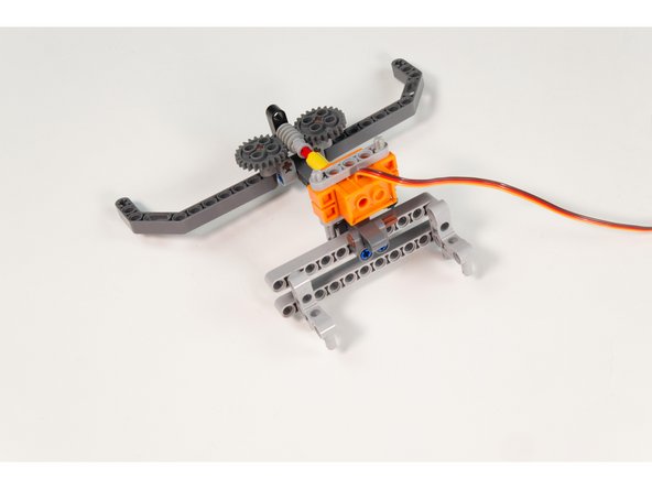
We’ve got our Gripper assembled, but we’re going to add a few more parts so we can easily mount it onto our Tank chassis.
-
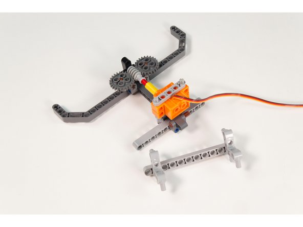
Grab the last LEGO Beam 11 and add 2 LEGO Cross Block Beam Bent 90 Degrees with 4 Pins . One at the end and one spaced one hole from the other end. (This will match the 10 hole wide frame of the Tank.)
-
Note that the assembly will wobble, but once we place it on the Tank it will be secure.
-
-
-
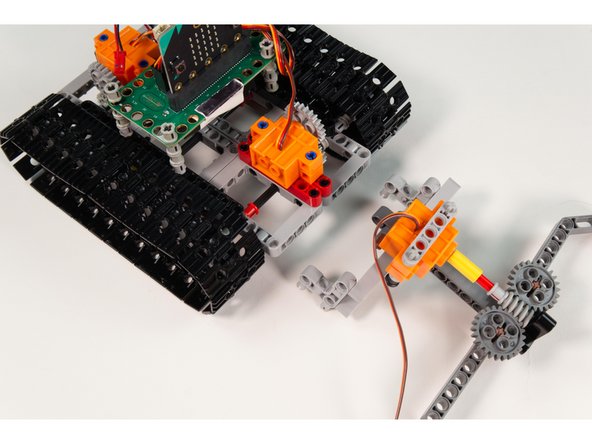
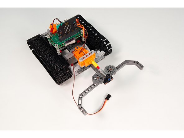
Attach the Gripper onto the front of the Tank.
-
It should line up with the beams. If not, make adjustment by moving the LEGO Cross Block Beam Bent 90 Degrees with 4 Pins as needed.
-
Okay! With our Gripper mounted to the tank we're ready to connect the servo so we can test it out.
-
-
-
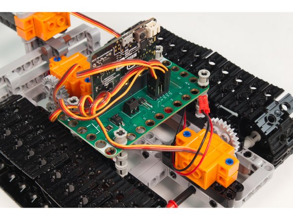
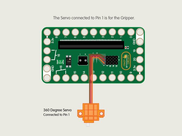
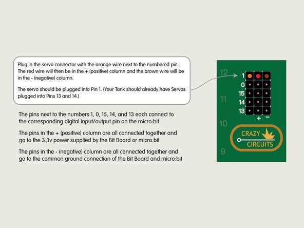
The servo should be plugged into Pin 1. (Your Tank should already have Servos plugged into Pins 13 and 14.)
-
Plug in the servo connector with the orange wire next to the numbered pins. The red wire will then be in the + (positive) column and the brown wire will be in the - (negative) column.
-
Now that our Gripper is ready to go and we’ve got it plugged into our Bit Board let’s load some test code so we can make sure it all works.
-
-
-
Connect a USB cable to the micro:bit and then plug it into your computer.
-
We'll be using makecode.microbit.org to program our board. It uses a simple drag and drop block interface.
-
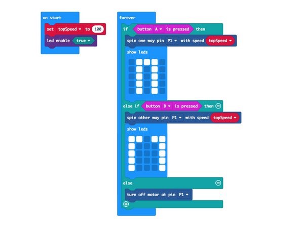
We're going to load the following code for our Gripper Setup program: https://makecode.microbit.org/_M4sEoucAW...
-
-
-
Press and hold Button A on the front of the micro:bit, then press and hold Button B.
-
Your Gripper should close and open when the respective buttons are pressed.
-
-
-
Let’s update the code for both the transmitter and the receiver so our Tank Gripper (and Tank) can respond to all of our controls.
-
For the Transmitter we'll load the code Tank RC Transmitter w/Gripper: https://makecode.microbit.org/_fkx5vqAvw...
-
For the Receiver we'll load the code Tank RC Receiver w/Gripper: https://makecode.microbit.org/_U36UbP1h0...
-
-
-
Now you can test your Gripper via Remote Control!
-
Pressing the left thumbstick down should result in the Gripper closing and pressing the right thumbstick down should result in the Gripper opening.
-
If the Gripper did not move as it should have, go through the steps again to make sure you've connected the servo and thumbsticks properly, and also make sure the code is loaded properly.
-
-
-
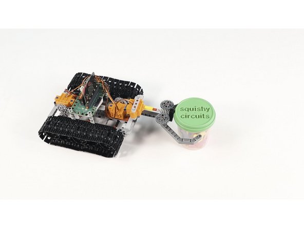
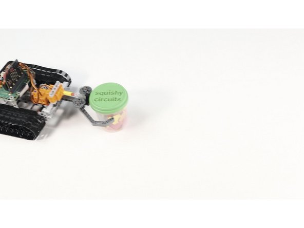
Your RC LEGO Tank with Gripper should be all ready to go!
-
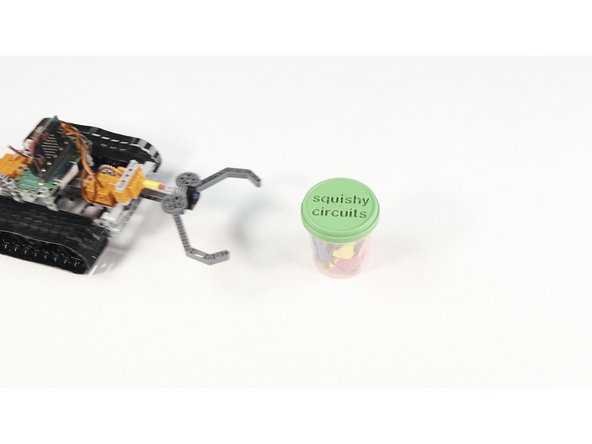
Create some fun challenges, like grabbing a cup or a can and moving it to a new location.
-
You could mark spots where the object needs to be moved from/to and time it to make a game.
-
Whatever you do with your RC LEGO Tank with Gripper, have fun!
-


Cancel: I did not complete this guide.
One other person completed this guide.
