Introduction
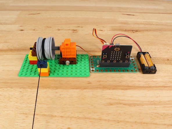
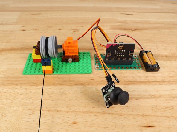
Build a simple LEGO Winch Mechanism and get it moving with the micro:bit and our Bit Board. This guide will cover using the micro:bit's built-in buttons, as well as connecting and using external buttons, a thumbstick, and a potentiometer.
Parts
- Crazy Circuits Bit Board
- micro:bit
- Brick Compatible 360 Degree Servo
- LEGO Wheel 43.2mm D. x 26mm Technic Racing Small with 3 Pinholes (41896)
- LEGO Axle 6 (3706)
- LEGO Axle Connector (Smooth with 'x' Hole) (59443)
- LEGO Axle 4 with End Stop (87083)
- LEGO Technic Brick 1 x 2 with Hole (3700)
- LEGO Technic Brick 1 x 4 with Holes (3701) × 3
- LEGO Technic Bush 1/2 with Teeth Type 1 (4265)
- String
- Maker Tape
- Standard Pushbutton Chip × 2
- Crazy Circuits Potentiometer Chip
- Thumbstick
- Misc LEGO Parts
Video Overview
Featured Document
-
-
As with all LEGO projects a variety of parts can be used. We've listed all the parts we chose but you should use what works, or what you already have on hand when possible.
-
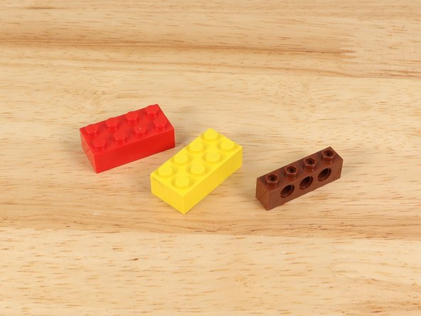
For instance, here are two alternative wheels/rims that could work.
-
-
-
Any wheel/rim with an "H" or "V" shaped groove should work. Avoid the ones with raised ribbing in the groove part.
-
Besides the specified LEGO parts you'll need a LEGO baseplate, a few standard LEGO bricks, a 360 degree continuous rotation servo, and some string.
-
-
-
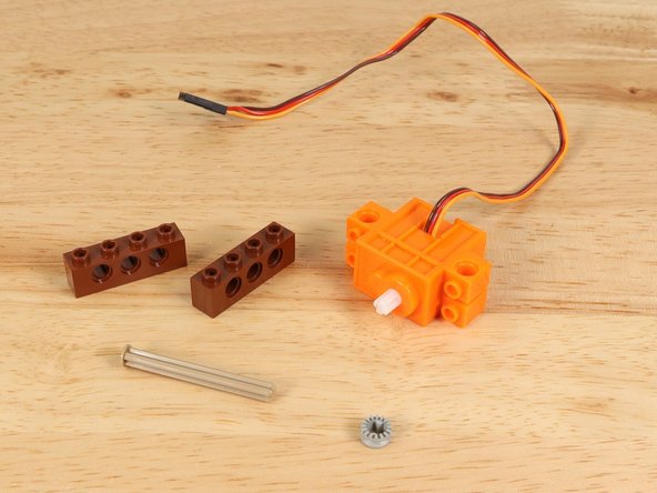
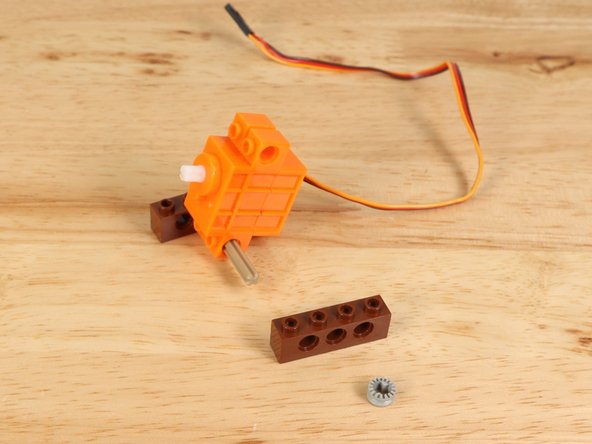
We'll start by adding some "feet" to the servo so we can attach it to the baseplate.
-
Use the following parts:
-
LEGO Technic Brick 1 x 4 with Holes (3701) You'll need two of them.
-
LEGO Axle 4 with End Stop (87083)
-
LEGO Technic Bush 1/2 with Teeth Type 1 (4265)
-
-
-
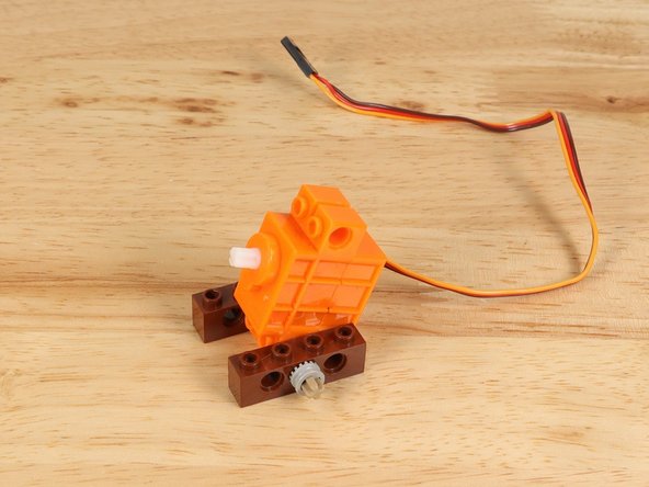
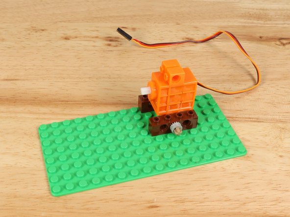
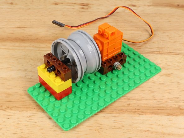
Once you have the "feet" for your servo you can attach it to a LEGO baseplate.
-
Make note of the orientation of the servo. Since the shaft is not centered you want it higher up in the assembly.
-
-
-
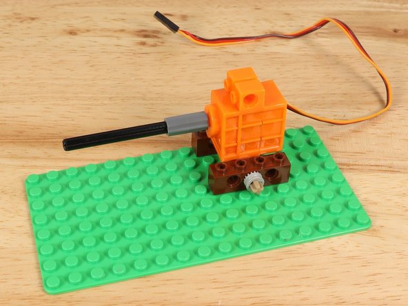
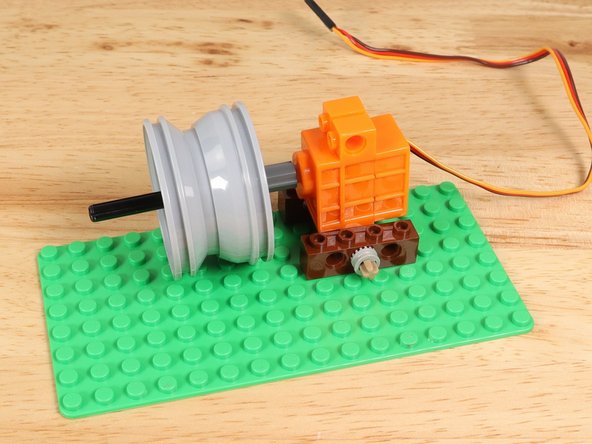
Next we'll attach the shaft and wheel/rim to the servo. You'll need an axle connector added to the servo shaft to start.
-
Use the following parts:
-
LEGO Axle Connector (Smooth with 'x' Hole) (59443)
-
LEGO Axle 6 (3706)
-
LEGO Wheel 43.2mm D. x 26mm Technic Racing Small with 3 Pinholes (41896)
-
Don't worry about the position of the wheel/rim on the shaft, since we can slide it into the correct position later.
-
-
-
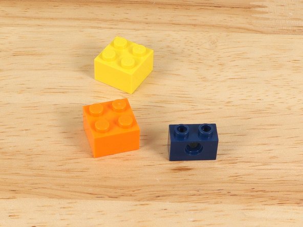
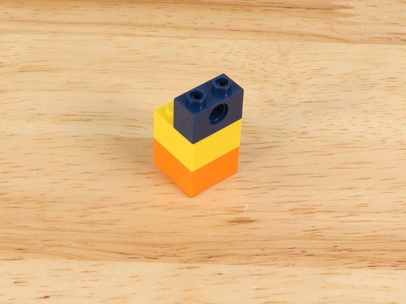
Next we'll add the parts to hold up the other side of the axle.
-
Grab two standard LEGO bricks and another LEGO Technic Brick 1 x 4 with Holes (3701).
-
Once assembled place it on the baseplate to hold the axle in place.
-
-
-
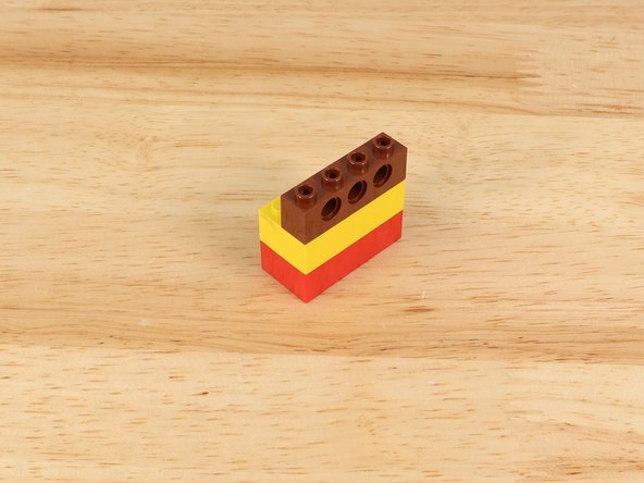
Next we'll add a simple guide for the string to feed through so it doesn't get tangled.
-
We used two small LEGO bricks and a LEGO Technic Brick 1 x 4 with Holes (3701).
-
Line it up with the wheel/rim as close as you can, then slide the wheel/rim so it is centered to match the guide hole.
-
-
-
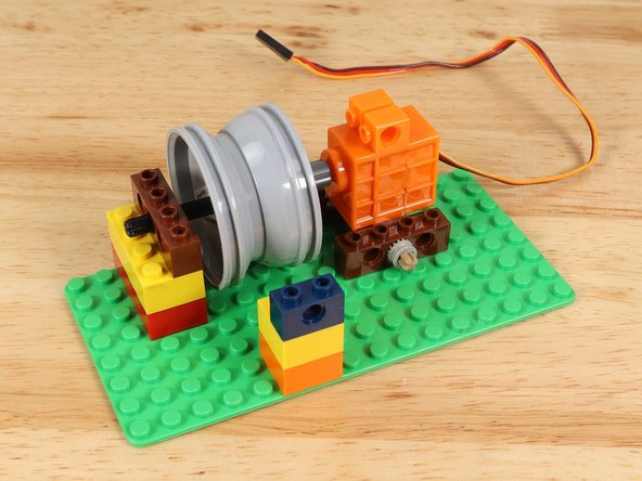
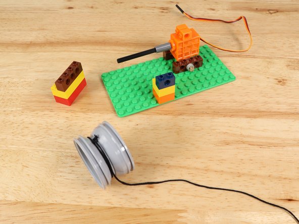
If everything looks right you can pull the wheel/rim off to add on some string.
-
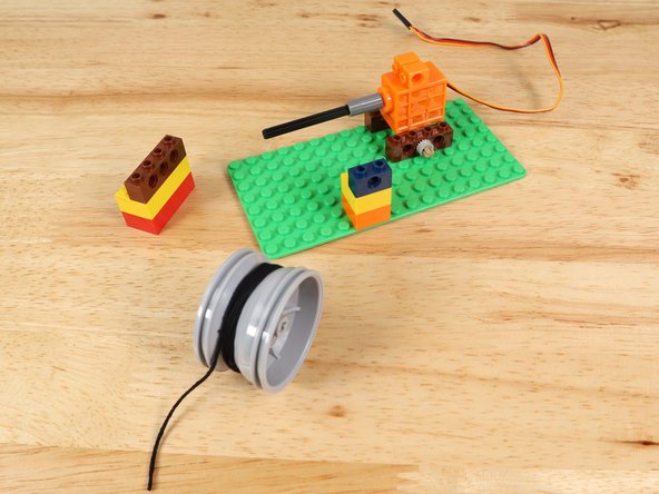
Tie the string tight onto the wheel/rim and wind it around a few times.
-
If your string isn't wound enough times it may not wind up properly if you let too much of it out. You can also add a small piece of tape to hold the string in place if your knot is not tight enough.
-
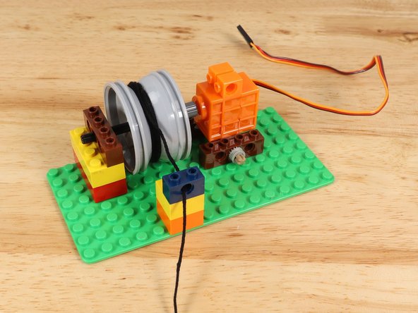
Place the wheel/rim back onto the axle and feed the string through the guide hole.
-
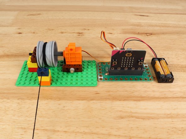
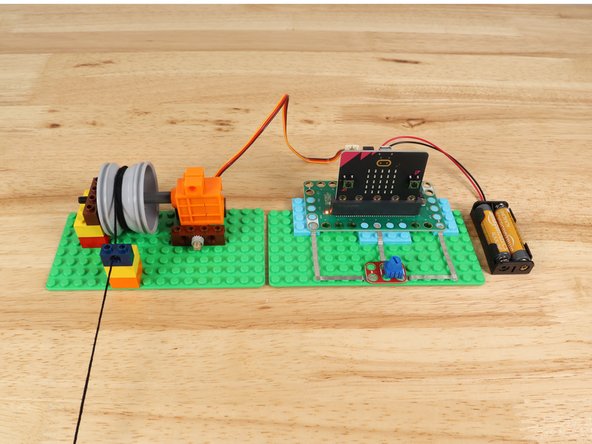
Your winch is ready to go!
-
-
-
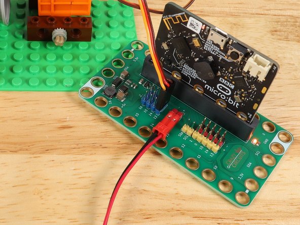
With our LEGO build complete we can add in our Bit Board and micro:bit so we can control things.
-
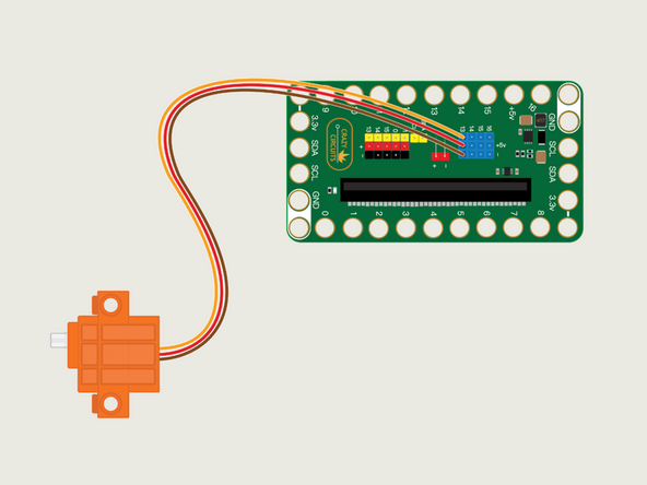
The servo has three wires connected to it that terminate in a black connector plug. This connector is what we will plug into the Bit Board header pins.
-
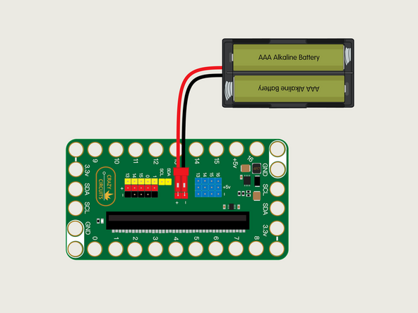
Connect the servo to Pin 13 on the Bit Board with the connector oriented so the orange wire is nearest to the number 13.
-
If you are using a V2 Bit Board plug the servo into the Blue Pins.
-
Make sure the brown wire of the servo connector is plugged into the - (negative) row and the red wire of the servo is plugged into the + (positive) row. The orange wire will be closest to the number 13 on the board.
-
-
-
We're going to show a few ways of controlling the winch, starting with the simplest first. This one requires no extra connections and uses the built-in buttons on the micro:bit
-
Connect a USB cable to the micro:bit and then plug it into your computer.
-
We'll be using makecode.microbit.org to program our board. It uses a simple drag and drop block interface.
-
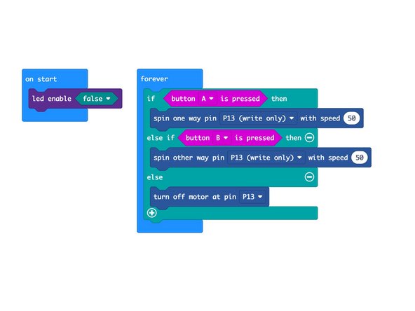
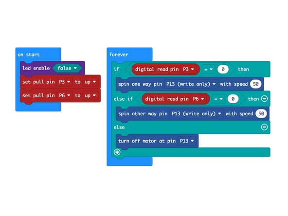
We're going to load the following code for our Winch Control program: https://makecode.microbit.org/_i1W402g7z...
-
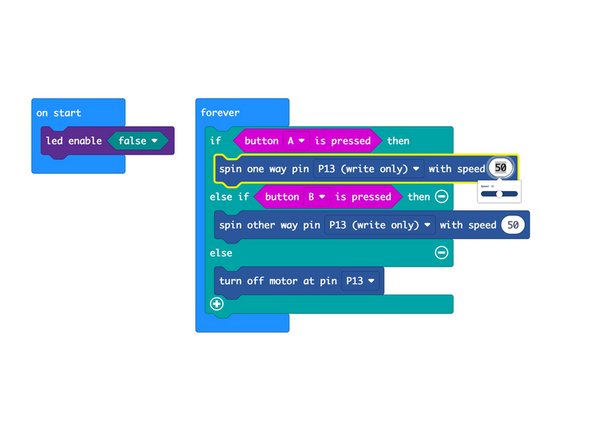
See the 50 in the spin command? You can change it! Just type in a new number, or click on it and you'll get a slider control to set the value, from 0 to 100. Maybe you want to run your winch really slow or... really fast!
-
-
-
Plug in the battery pack to provide power to the servo and try pressing button A or B on the front of the micro:bit
-
The servo should turn forwards or backwards for each of the button presses. As long as you press and hold it will continue to turn.
-
If everything worked as expected we'll add in some buttons using Maker Tape and a LEGO baseplate and then load new code to support the new components.
-
-
-
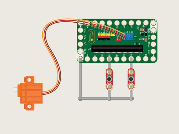
We're going to use a LEGO baseplate to attach the Bit Board and two buttons with Maker Tape.
-
Refer to the diagram for an overview of the connections, and the PDF for a more detailed explanation.
-
-
-
Load the code the same way you did for the previous program. This time we'll use our Winch Control Buttons program: https://makecode.microbit.org/_5aM2Ft0sT...
-
Once you have your code loaded you can test it out. It should work just like it did with the micro:bit's built-in buttons.
-
Using the Crazy Circuits buttons along with Maker Tape allows you to see the circuit in a way you can't with the built-in buttons.
-
What happens if the tape isn't connected properly? Does your circuit still work?
-
-
-
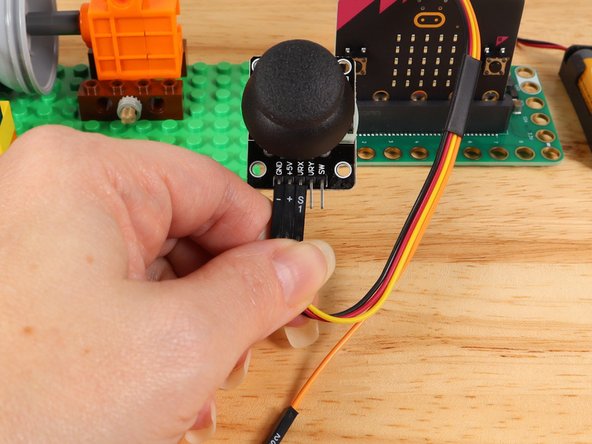
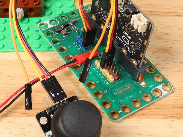
For the thumbstick we don't need any Maker Tape or a LEGO baseplate. We'll just plug the thumbstick into the pin headers on the back of the Bit Board using the Crazy Circuits Ribbon Cable.
-
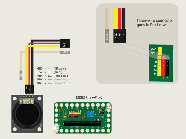
The end with S1, +, and - can plug directly into the Pin 1 row (make sure S1 goes into 1).
-
If you look at the pins on the Thumbstick you'll see +5V, VRX, and GND (pins labeled VRY and SW will not be used in this guide). S1 connects to VRX, + connects to +5V, and - connects to GND.
-
We only need three wires for the Thumbstick in this guide so you can leave S2 (the Orange wire) unconnected.
-
The pushbuttons are digital, in that they are either on or off, and there is no in-between. The thumbstick is an analog device, and will send a value between 0 and 1023 to the micro:bit depending on how you move it.
-
-
-
Load the code the same way you did for the previous program. This time we'll use our Winch Control Thumbstick program: https://makecode.microbit.org/_1UAM5jeV7...
-
Once you have your code loaded you can test it out. While the control is different (a thumbstick as opposed to pushbuttons) the functionality of the winch should be the same. It will spin backwards or forwards at the speed that is set in the code.
-
-
-
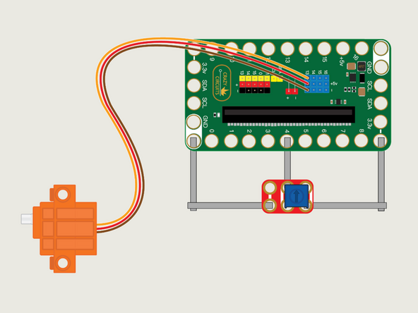
So far we've just made our winch go backwards and forwards, and we've seen where we can adjust the speed in the code, but let's try to adjust the speed with a potentiometer.
-
The potentiometer is similar to the thumbstick in that it's an analog input and instead of looking for an on or off like the pushbuttons, we are looking for a value. We'll also use that value to adjust the speed of the servo.
-
Refer to the diagram for an overview of the connections, and the PDF for a more detailed explanation.
-
-
-
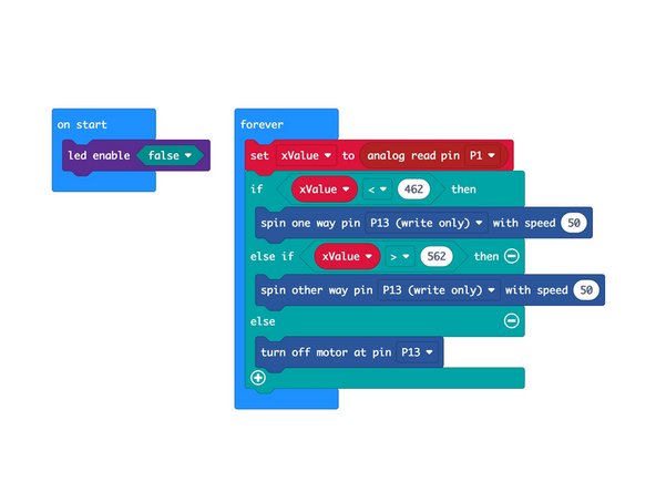
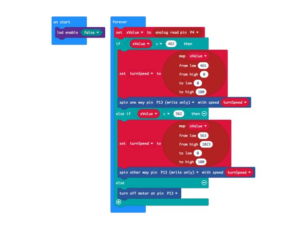
Load the code the same way you did for the previous program. This time we'll use our Winch Control Potentiometer program: https://makecode.microbit.org/_EF9gxJcwT...
-
Our potentiometer code is a bit more complex than the thumbstick code, though some of the functionality is the same.
-
For this code we're capturing the analog value and then using it to adjust the speed at which our winch turns.
-
If you start with the potentiometer centered and then turn either clockwise or counterclockwise it will cause the servo to start turning, and increase speed the further you turn it.
-
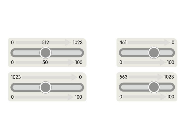
We're using the map function in our code. Refer to the PDF for a detailed explanation of how it works to map one scale onto another scale.
-
What if we use this code with the thumbstick? Will it respond the same way?
-


With this guide you should now understand multiple ways of controlling a 360 degree continuous rotation servo using pushbuttons, a thumbstick, and a potentiometer. MakeCode is an easy way to use existing code and make changes to it so you can test how those changes affect what happens with your circuit.
With this guide you should now understand multiple ways of controlling a 360 degree continuous rotation servo using pushbuttons, a thumbstick, and a potentiometer. MakeCode is an easy way to use existing code and make changes to it so you can test how those changes affect what happens with your circuit.
Cancel: I did not complete this guide.
One other person completed this guide.
Attached Documents
