
Introduction
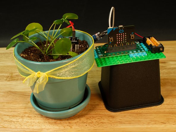
Connect a Moisture Sensor to the Bit Board so your micro:bit can let you know when you need to water your plant.
Video Overview
Featured Document
-
-
A Moisture Sensor is capable of reading the conductivity between two legs of a probe inserted into soil or other material that contains moisture.
-
Basically, a small electrical charge travels from one leg of the probe to the other and the resistance is what is measured.
-
The control board that the probe plugs into can output a voltage which can then be read by an analog pin on a microcontroller.
-
After reading the sensor the micro:bit will show a value between 0 and 1023. In the case of this sensor, 1023 is maximum resistance (or no current flowing) and 0 is no resistance (or maximum current flowing).
-
For our use, 1023 would mean the probe is inserted into dry soil. Not good for a plant! If we get a reading less than 400 it means our soil is pretty wet.
-
-
-
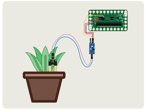
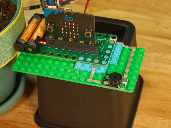
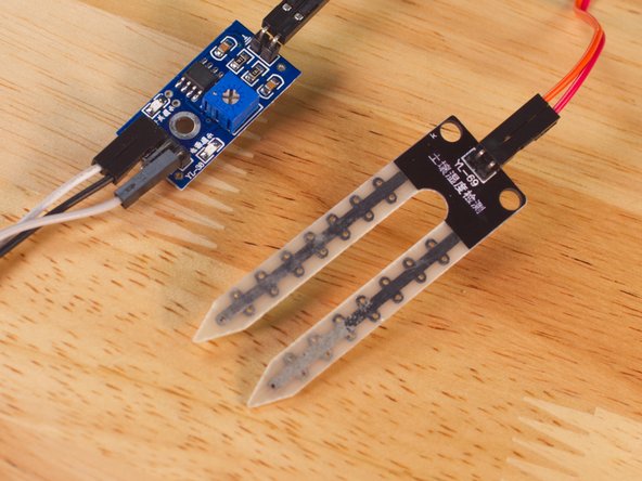
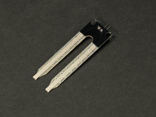
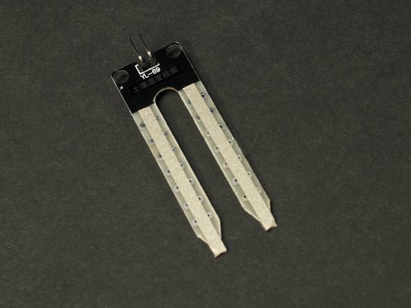
The Moisture Sensor consists of two parts, the YL-38 control board, and the YL-69 probe. The probe connects to the control board with two F/F Jumper Wires, and then the control board connects to the Bit Board with three F/F Jumper wires.
-
We use a + (positive) and - (negative) pin on the Bit Board to power the control board, and then connect the AO pin on the control board to Pin 1 on the Bit Board so we can read the analog value coming from the sensor.
-
The + (positive) pin can plug into any + pin in the positive column, and the - (negative) pin can plug into any - pin in the negative column.
-
You don't need to align the pins in a row. The wire from the AO pin must go to Pin 1, but the positive and negative can go to any positive and negative pin, respectively.
-
-
-
If you've never used a micro:bit before you'll want to check out this guide: Bit Board V2 Setup and Use
-
We're going to load the following code for our Moisture Sensor Reading program: https://makecode.microbit.org/_CCpgM4Eat...
-
The code is very simple. It's going to turn on the LED matrix on the micro:bit, and then read and show the value it gets from the Moisture Sensor by scrolling it across the LEDs on the micro:bit
-
-
-
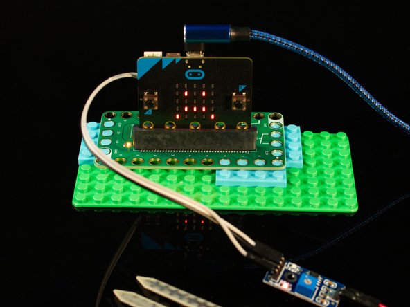
Once you've got your Moisture Sensor connected and you load the code you should see a number scroll across the LED matrix. It will probably be “1023” if you haven’t inserted the probe into anything.
-
If you do not see 1023 scroll across the LED matrix, check your wiring. Make sure everything is plugged into the correct place.
-
-
-
We can provide power to the micro:bit and Bit Board by using a USB cable (which we used for programming the micro:bit in a previous step) or by using a 2 AAA Battery Pack.
-
The USB cable provides 5 volt power from a computer or USB wall adapter or battery pack, and the voltage regulator on the micro;bit drops the 5 volts down to 3.3 volts to provide power.
-
A battery pack with two AAA batteries provides just over 3 volts when using two fresh alkaline batteries. This also helps if you want your project to be a bit more portable.
-
-
-
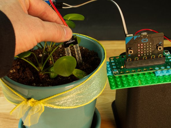
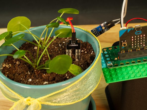
Now that we are seeing readings from the Moisture Sensor, we should insert the probe into some soil!
-
Grab your favorite houseplant and push the probe into the soil. You should start to see a new value scroll across the LED matrix on the micro:bit (unless the soil is too dry!)
-
-
-
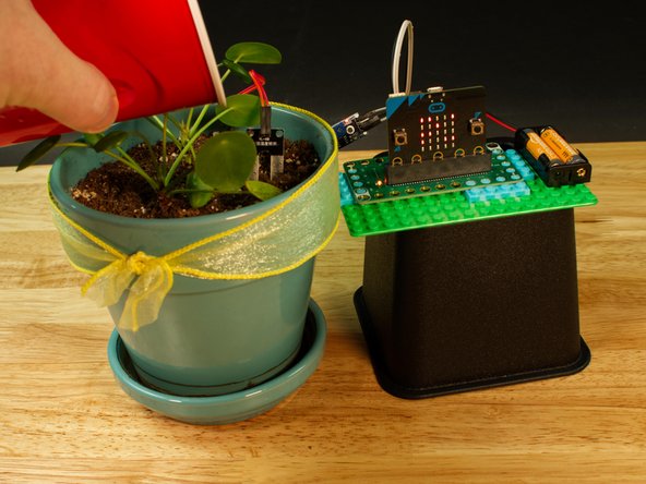
For this step it may take a bit of trial and error to get it just right. If your soil is too dry (based on what your plant needs) add some water. You should see the value displayed on the LED matrix get lower.
-
Warning! Water and electronics do not mix! While the Moisture Sensor is meant to be in wet soil, water should not touch other parts of your electronics. Be careful around the probe wires, the control board, and your micro:bit
-
Once you have your plant soil to a state that you consider wet enough, make note of the number. For our plant it was around 700.
-
-
-
Now that we've seen the Moisture Sensor in action, let's try some new code!
-
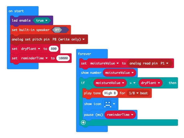
We're going to load the following code for our Moisture Sensor Alarm program: https://makecode.microbit.org/_RXkYgP7L6...
-
For this version we have two variables to consider: dryPlant and reminderTime
-
The dryPlant variable will be set higher than the number we determined in our calibration step. Since we found 700 to be a good amount of moisture for the soil, we'll use 800 for our threshold.
-
The reminderTime variable will set how often we see the sad face on the LED matrix and hear a beep.
-
And yes! We are going to add an alarm as well. See the next step!
-
-
-
We're going to add a Crazy Circuits Piezo Speaker to our circuit, using some 1/8" Maker Tape.
-
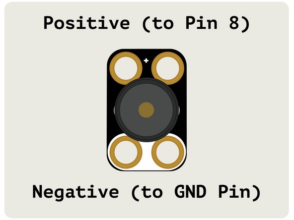
Connect the Piezo Speaker between Pin 8 and GND. (Make note of the polarity!)
-
Now when the soil is too dry (based on the number you assigned to dryPlant you will see a sad face, and hear a beep. This will happen every 10 seconds (or whatever interval you set for the reminderTime variable.)
-
-
-
While these Moisture Sensors are cheap (we got a 5 pack for less than $8) they use resistive measurement, which means that eventually one of the probe legs will corrode to the point that it will no longer work. We've got a good workaround though, using Maker Tape!
-
We used 1/8" Maker Tape and just wrapped a piece around each of the probe legs. Since Maker Tape is conductive on both sides and all the way through, it will conduct and protect at the same time.
-
If you see the Maker Tape start to wear out or corrode, it's a simple process to peel it off, remove any residue, make sure the probe is nice and dry, and then put a new piece in place.
-
Make sure you do your calibrations after you attach the tape, as it may slightly affect the reading from the sensor.
-


Attached Documents
