Introduction
The micro:bit can use PWM (Pulse Width Modulation) to control LEDs, servos, and other components. You can see what a PWM signal looks like with an Oscilloscope.
Video Overview
Featured Document
-
-
Pulse Width Modulation (PWM) is a way of reducing the power delivered by an electrical signal, by effectively breaking it up into discrete parts. The average value of voltage fed to the circuit is controlled by turning it on and off at a fast rate. The longer it is on compared to the off periods, the higher the power supplied to the load.
-
If a PWM signal is used with an LED the observed outcome is that the LED appears to be dimmer (as compared to full brightness) when the duty cycle is less than 100%.
-
If a PWM signal is used with an electric motor the observed outcome is that the motor slows down (as compared to running at full speed) when the duty cycle is less than 100%.
-
In the case of an LED, the speed at which the LED is turned on an then off is so fast the human eye cannot detect it, and the LED appears dim rather than to be blinking on and off.
-
In the case of an electric motor, the power switching on and off at a fast rate (the pulsing of power) causes the motor to not have constant power, but inertia keeps the motor moving while it is not receiving power.
-
-
-
An oscilloscope is an electronic test instrument that graphically displays varying signal voltages, usually as a calibrated two-dimensional plot of one or more signals as a function of time. The displayed waveform can then be analyzed for properties such as amplitude, frequency, rise time, time interval, distortion, and others.
-
The oscilloscope can be adjusted so that repetitive signals can be observed as a persistent waveform on the screen. A storage oscilloscope can capture a single event and display it continuously, so the user can observe events that would otherwise appear too briefly to see directly.
-
-
-
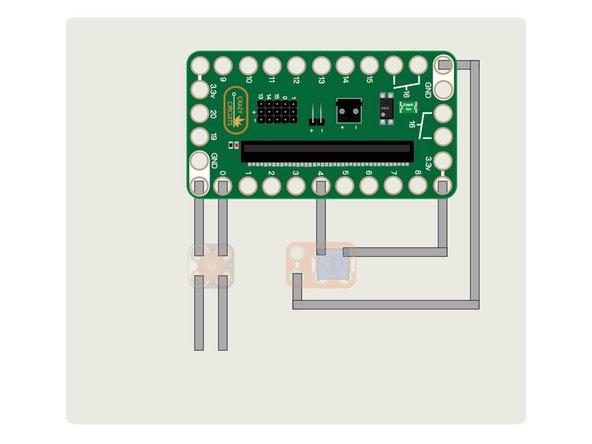
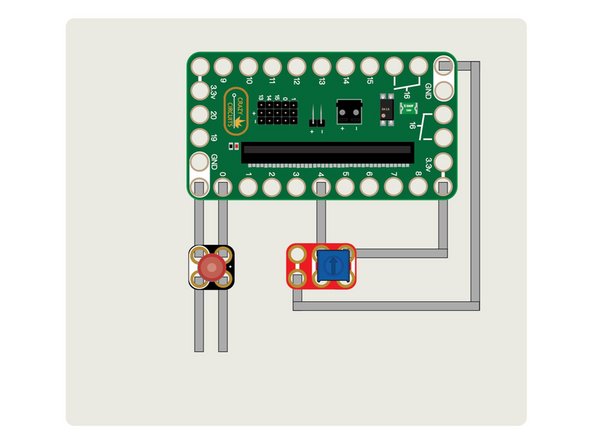
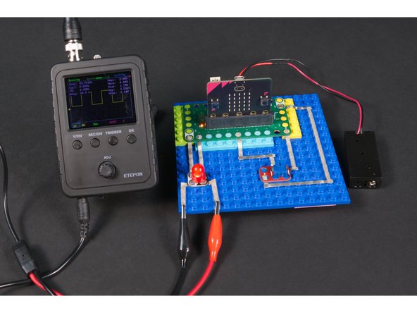
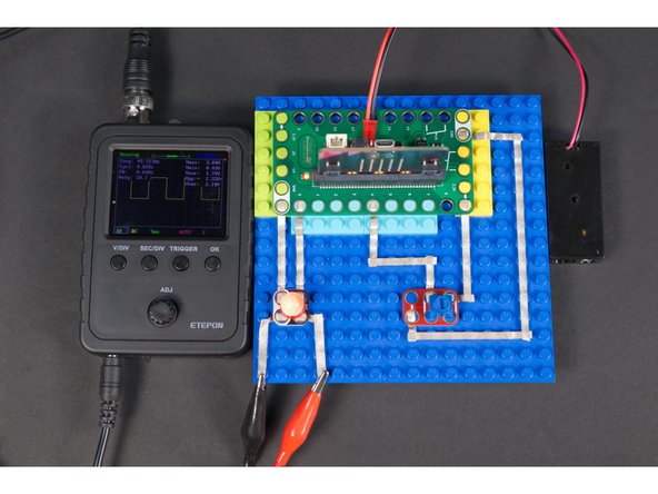
Place the Bit Board onto a LEGO baseplate and connect the two components using 1/8" Maker Tape.
-
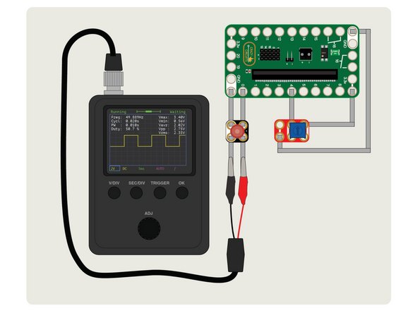
The LED is connected to GND and Pin 0. (Make note of the polarity, since the LED will not work if connected backwards.)
-
The potentiometer will be connected to GND, Pin 4, and 3.3V. Current flows through the potentiometer from 3.3V to GND and turning the knob changes the resistance, which is detected by Pin 4.
-
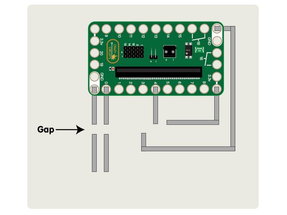
Attach two extra pieces of Maker Tape on the other side of the LED so you can connect an oscilloscope later.
-
The attached PDF has more detail on the circuit and connecting everything together.
-
-
-
Connect a USB cable to the micro:bit and then plug it into your computer.
-
We'll be using makecode.microbit.org to program our board. It uses a simple drag and drop block interface.
-
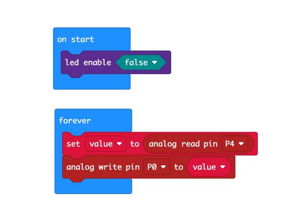
We're going to load the following code for our PWM Output program: https://makecode.microbit.org/_YpPPvPP2p...
-
You can continue to power this circuit using the connected USB cable, or you can use a 2 AAA battery pack.
-
-
-
Once you've got the code loaded and power for your circuit you can test it out.
-
The potentiometer should cause the LED to shine brighter or dimmer depending on which way you turn it.
-
If the LED gets dimmer instead of brighter when you turn it clockwise you can just remove the potentiometer, rotate it 180 degrees, and then put it back in the circuit.
-
If your circuit works as expected, you can move on to connecting the oscilloscope.
-
-
-
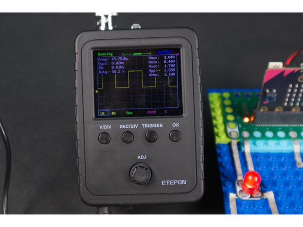
We used our (very cheap) oscilloscope connected to GND and Pin 0 so we could see the PWM signal that was being sent to the LED.
-
Red goes to the positive side of the signal (in this case Pin 0) and black goes to the ground (GND) side of the signal.
-
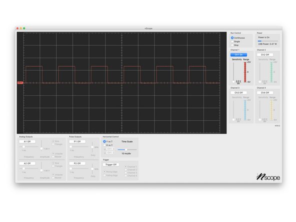
This guide won't go in-depth into using an oscilloscope, but with the less expensive models there are typically just a few settings to adjust, so getting to see a square wave output isn't too difficult.
-
Oscilloscopes can range from fairly cheap one channel models (often found as kits needing assembly) to multi-channel units that cost thousands of dollars and connect to computers with special software. For our experiments here an inexpensive single input scope worked just fine.
-
-
-
As you adjust the Potentiometer you'll see the LED change brightness, and if you've got your Oscilloscope connected properly you should also see a square wave.
-
PWM works by turning the power to the circuit on and off very rapidly. It's so fast that the human eye can't detect the on/off cycle and the LED appears to be dimmer, not blinking on and off.
-
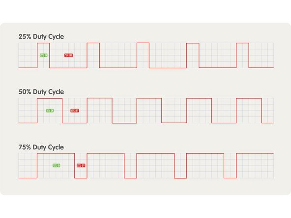
The Duty Cycle of the PWM signal refers to how long the circuit is on versus how long it is off.
-
The attached PDF goes further explaining how PWM, waves, and duty cycle work.
-
-
-
While the micro:bit supports PWM on (almost) every pin, other controllers will only support PWM on specific pins, so always make sure you are using an appropriate pin if you want to use PWM.
-
You may have noticed that in the code the statement to use PWM is analog write. This is common in other environments as well. PWM is basically a way to simulate an analog output with a digital method.
-
An oscilloscope can be useful for troubleshooting and debugging circuitry, but as we've seen here is also useful for visualizing a digital signal. (But don't worry! You can still do plenty of circuit building and troubleshooting without an oscilloscope.)
-


