Video Overview
Video Overview:
Featured Document
-
-
Before continuing with this tutorial, build the Tank Body here: Rover Tank Body
-
-
-
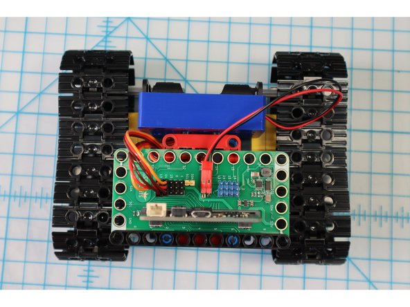
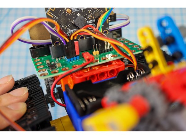
To add the paper robot template, we'll need to adjust the angle of the battery pack by switching out the pins.
-
Disconnect the battery pack and remove the black pins.
-
-
-
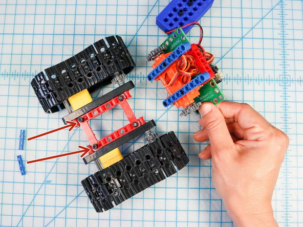
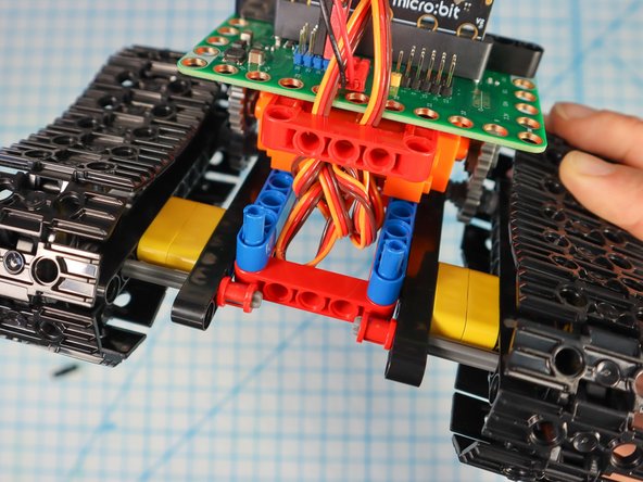
Separate the tank where the blue beams meet the red frame.
-
Remove the two pins at the rear of the tank as shown.
-
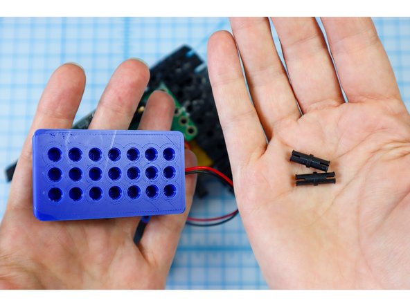
Replace the black pins with blue pins.
-
Reconnect the blue beams, pushing the blue pins through the last hole as shown.
-
-
-
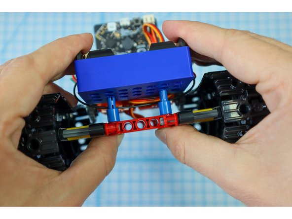
Place the battery pack over the pins with the batteries facing up.
-
-
-
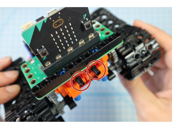
Add two black pins to the front as shown.
-
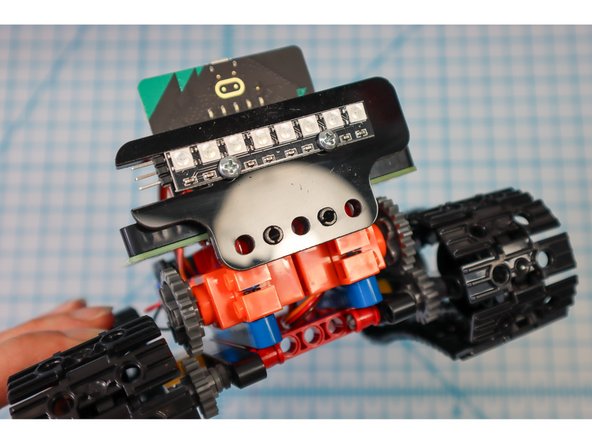
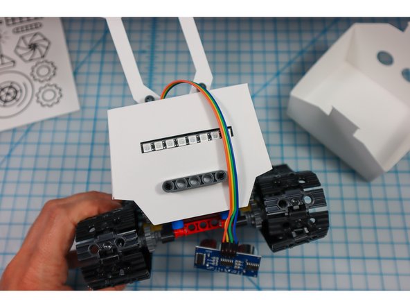
Attach the NeoPixel Strip.
-
-
-
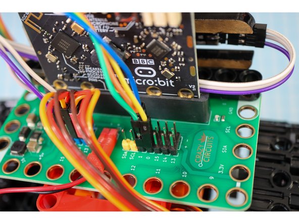
Add three wires to the NeoPixel strip and connect them like this: IN to Pin 16, VCC to +5V and GND to "-".
-
-
-
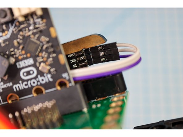
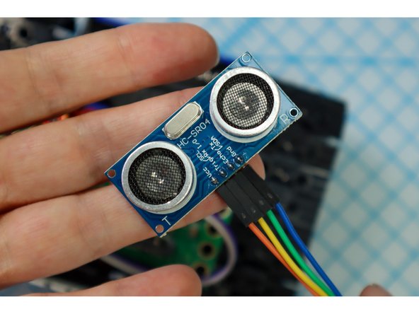
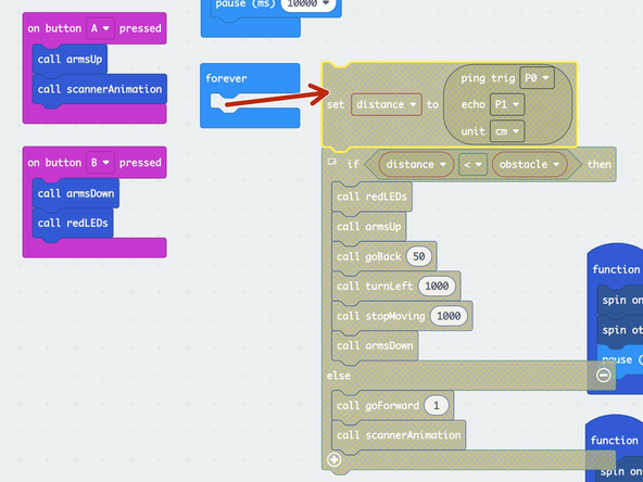
Add wires to the Distance Sensor and connect them like this: VCC to "+", Trig to Pin 0, Echo to Pin 1, GND to "-".
-
-
-
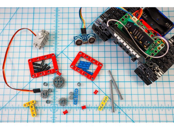
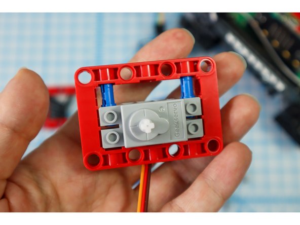
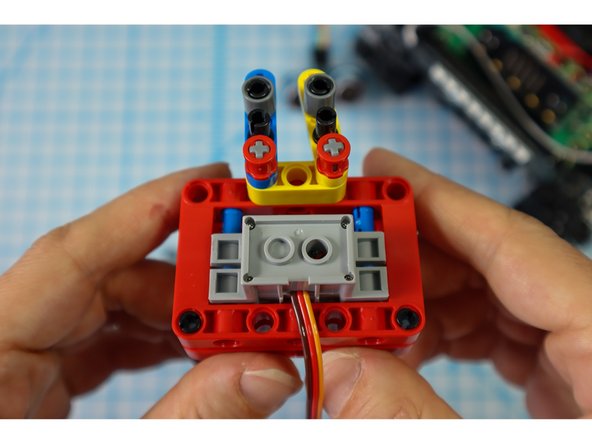
Get a red frame piece, two long pins, and the gray servo motor.
-
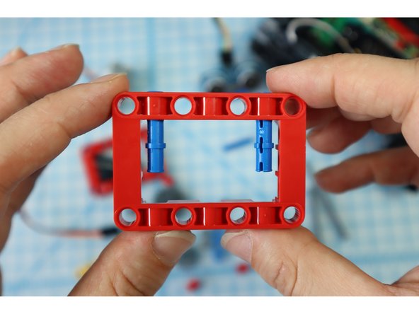
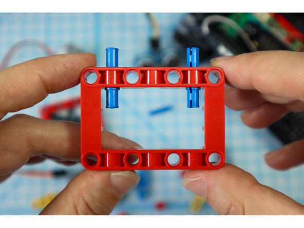
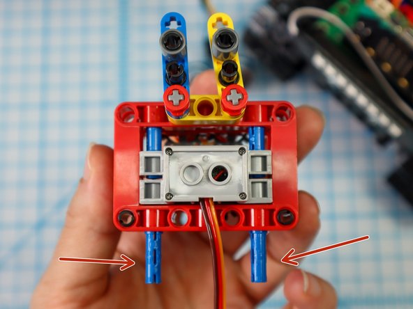
From the inside of the frame, insert the blue pins "long-side-in-first" as shown.
-
Position the servo motor inside the frame so that the holes align with the blue long pins.
-
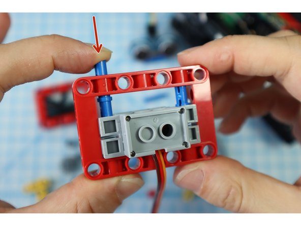
Press the pins down from the outside of the frame causing them to slide into the holes in the motor as shown.
-
Note: The blue pins will only go through the motor halfway. This is a bit of a nontraditional build strategy, but it works for our purposes!
-
-
-
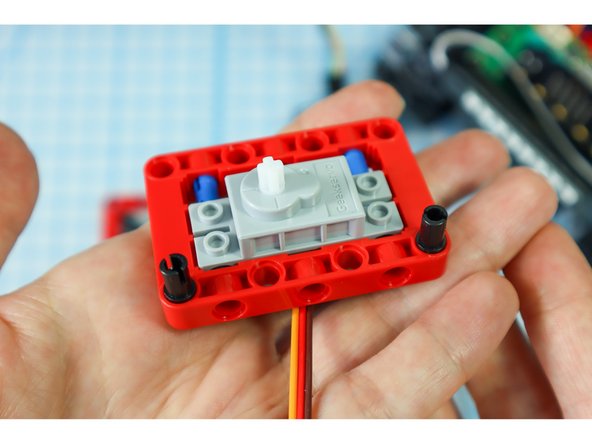
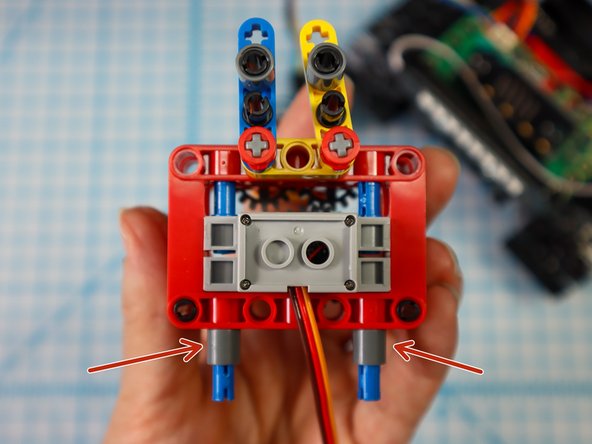
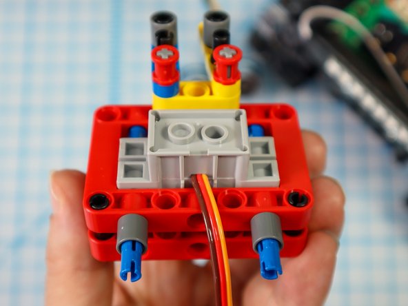
Add two black pins to the bottom of the frame, on the same side as the motor as shown.
-
-
-
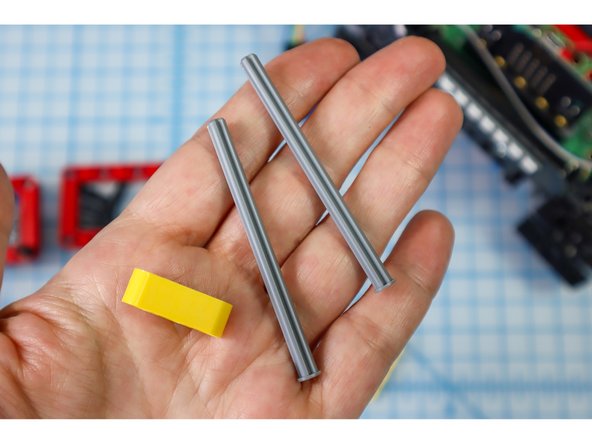
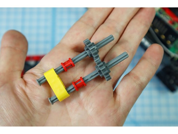
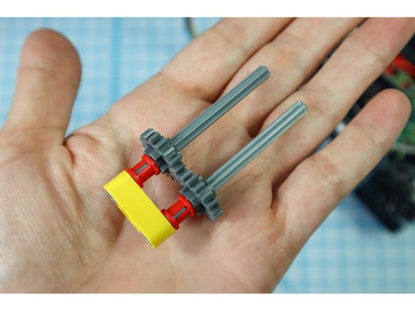
Insert the axles with flat ends into the outer holes of the yellow beam, and thread on the other components as shown: full red bushings, and small gears.
-
Push the pieces down until they stop, interlocking the gears.
-
-
-
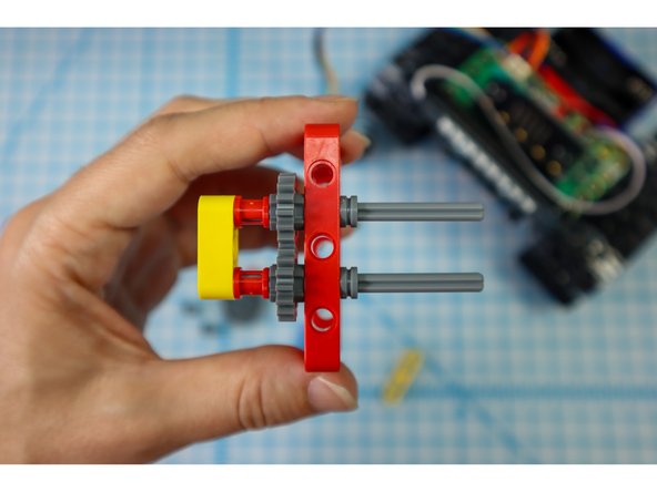
Push the axles through a red frame, then add half bushings to the gray axles to secure it.
-
Thread the axles through the existing red frame motor assembly as shown.
-
Note: The black pins won't be fully inserted into the red frame, they are just there for some extra stability.
-
-
-
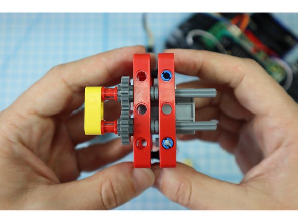
Continue adding components to the axles as shown: the yellow beam, a half beam on each axle, and full red bushings on each axle.
-
-
-
If you turn the gears so that the two half-height beams meet, they should be as symmetrical as possible. They won't be perfect but they should be close.
-
You may need to adjust the gear's relationship to one another by loosening the parts and realigning the gears.
-
-
-
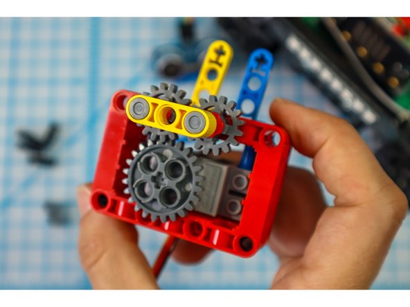
With the other gears aligned, add the main gear to the motorhead. The main gear should connect with one of the two smaller gears.
-
-
-
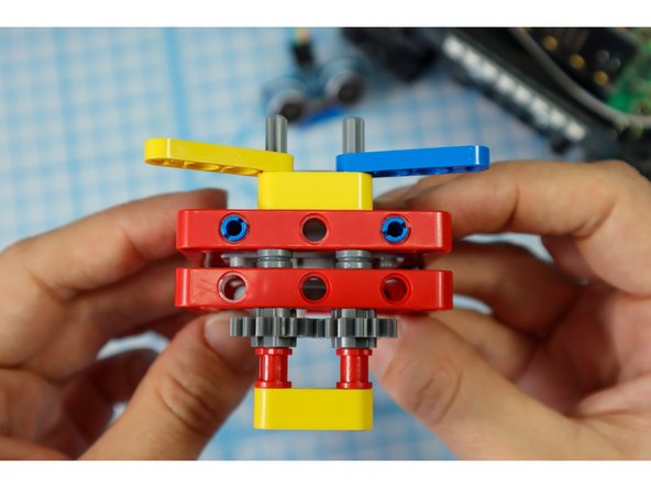
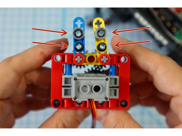
Add 4 black pins to the holes in the half beams as shown.
-
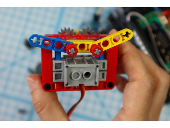
Add a single beam to the top pins as shown. These will connect to the paper arms in a later step.
-
-
-
Add blue pins to the bottom as shown.
-
Place single beams on each of the pins.
-
-
-
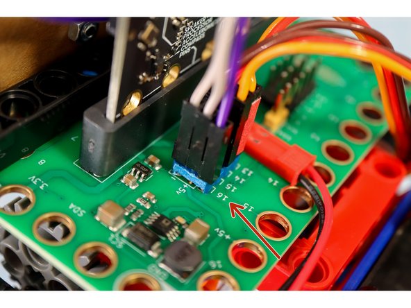
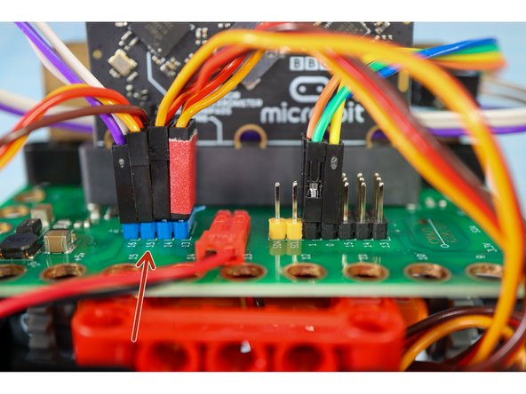
Connect the motor wires to Pin 15 as shown.
-
-
-
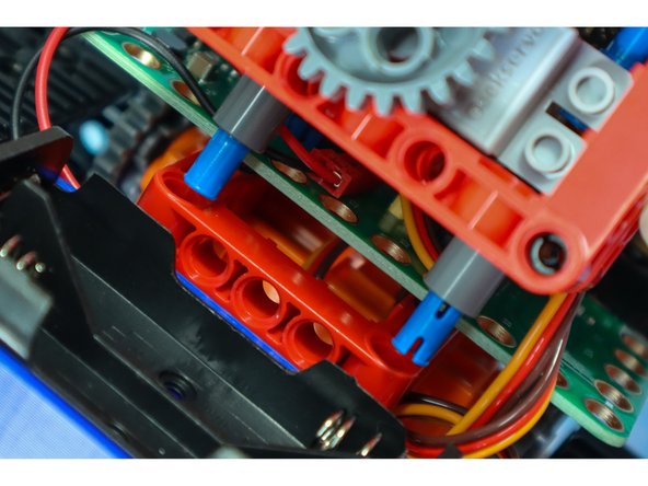
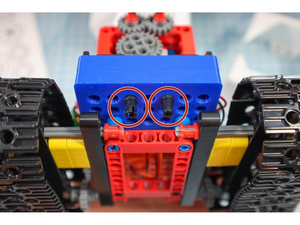
Connect the gear assembly to the red fame on the body as shown.
-
-
-
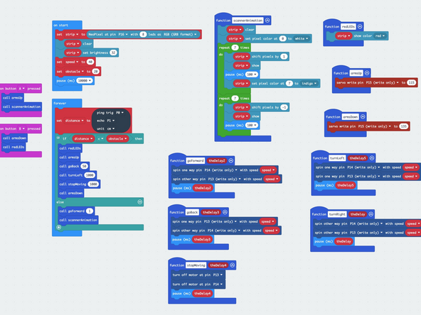
Download the code to the micro:bit https://makecode.microbit.org/_LADHXq6DX...
-
Hint: To make the build easier, drag the blocks out of the forever loop while building to stop the bot from "running away!"
-
-
-
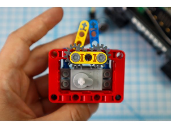
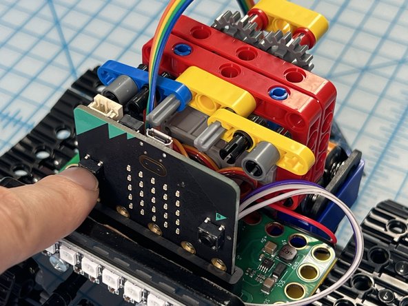
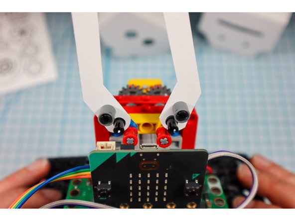
The code is set up so that you can press button "A" to move the arms to the up position and press button "B" to move the arms to the down position. The down position is default.
-
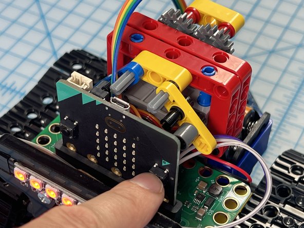
Adjust the gears so that when you press "A" the starting angle looks like photo 1 and when you press "B" the end angle looks like the second photo.
-
Tip: An easy way to do this is to remove the large gear, position the "arms" and reconnect the large gear again.
-
-
-
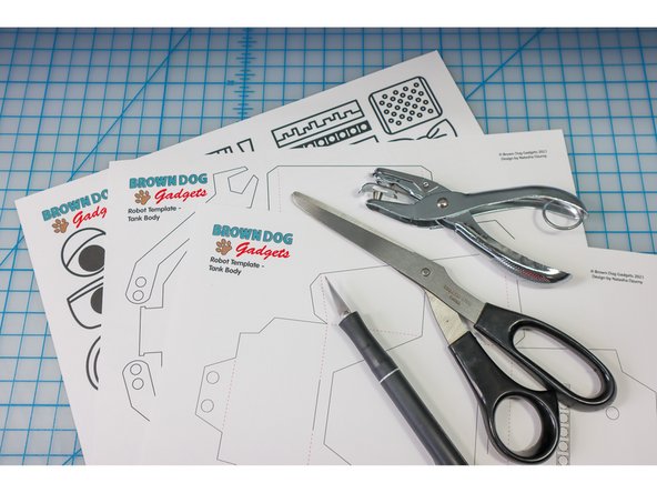
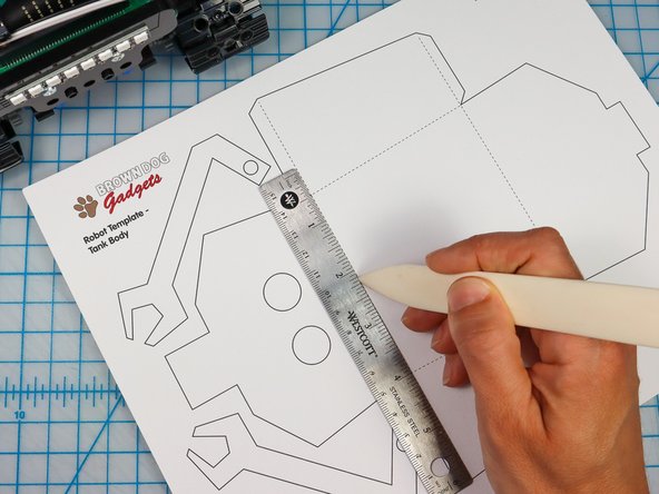
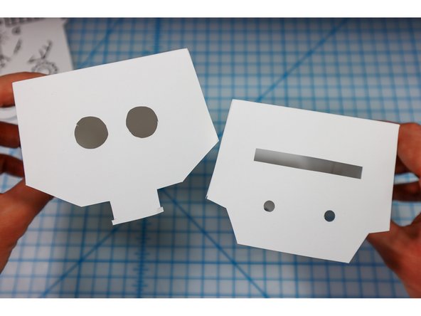
Print out the template on heavy paper or cardstock.
-
You might choose to print the template on colored paper to give your bot some personality!
-
-
-
Use a bone folder or pen to score along the dotted red lines to make it easier to fold later.
-
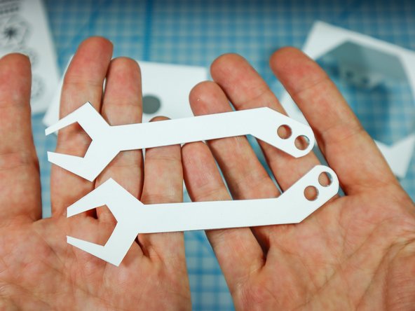
Cut out the head and body template along the solid lines using a craft knife for the interior shapes and scissors or a craft knife for the perimeter.
-
On the body, the location of the NeoPixel strip is shown. You could choose to cut it out or to let the LEDs shine through the paper. I chose to cut mine out to see the location of the LEDs easily.
-
-
-
Use a hold punch to punch out the holes in the arms and the 4 holes on the body.
-
-
-
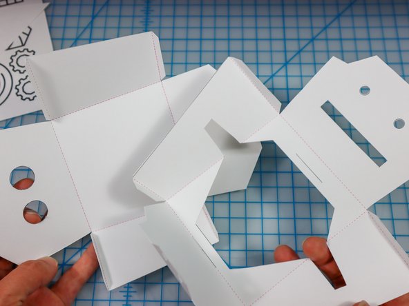
Fold along the dotted lines so that the dotted lines will be on the inside of the project.
-
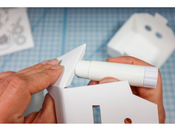
Fold each of the flaps down and apply glue to the outside.
-
Glue the flaps on the inside of each corner as shown to create both the head and the body.
-
-
-
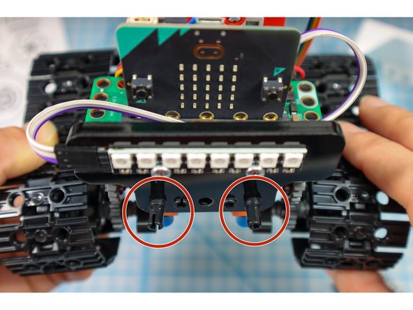
Add 2 pins to the front and 2 pins below the battery pack as shown. This will be where the paper body is attached.
-
-
-
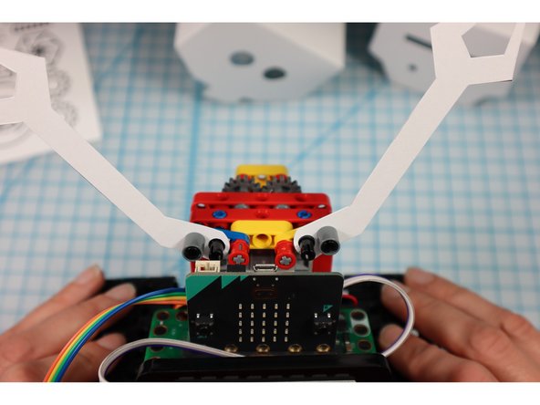
Disconnect the pins and place the arms onto the half beams. Then, replace the pins.
-
-
-
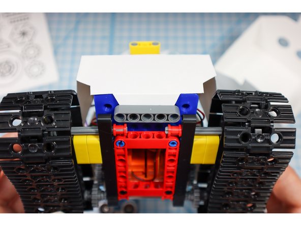
Place the paper body over the bot (hint: put the arms up and thread the Distance Sensor through the hole before wrapping it around.
-
Use gray beams to hold the body in place as shown.
-
-
-
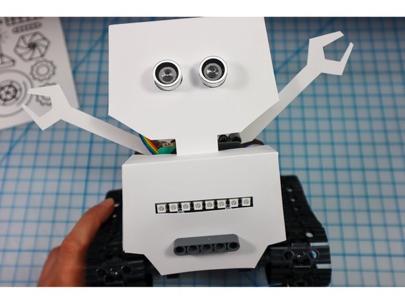
Place the ping sensor into the eye circles as shown.
-
If the eyes fall out of place easily, add a piece of tape to the inside.
-
-
-
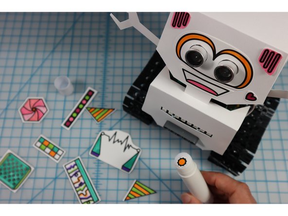
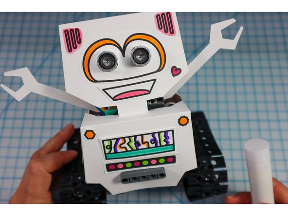
Color in the robot embellishments and glue them to the bot. What type of personality will your bot have?
-
-
-
If you haven't already, add batteries by opening up the paper body from the back.
-
If you haven't already, drag the code blocks back to the forever loop and re-download the code.
-
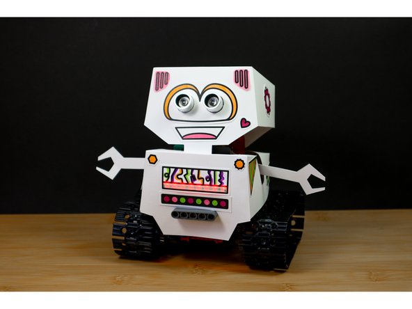
Now, take your 'bot for a spin!
-
Share your finished bot with the world by tagging us #BrownDogGadgets
-
-
-
When you are done playing with your bot, we recommend turning it off by removing the batteries rather than disconnecting the battery holder.
-
Open the back of the Bot's body and lean it forward to take the batteries out.
-
-
-
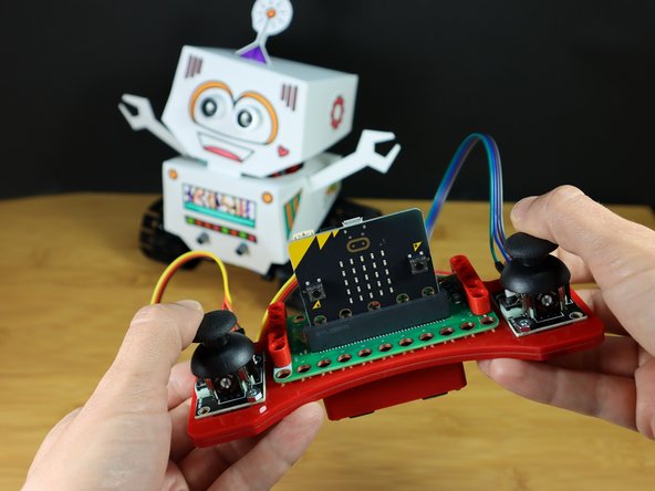
To make a remote control for your bot, continue with this tutorial: Robot - Remote Control - Tank Body
-


Attached Documents
