
Introduction
If you've built our Rover Main Body you can add two IR Sensors so your Rover can become a line following robot.
Video Overview
-
-
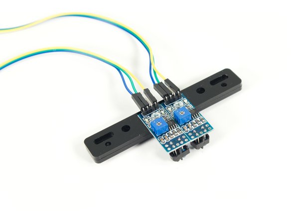
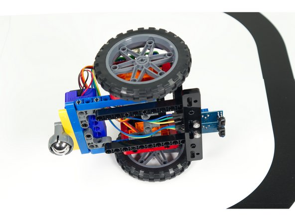
With the addition of the Light Following Bar our Rover can function as a Line Following Robot.
-
The two sensors on the bar detect light (white) or dark (black) on the mat by shining IR (infrared) light on the surface and then measuring how much light is reflected back.
-
The Emitter is an LED that shines infrared light and the Receiver is a photodiode sensor that can detect infrared light.
-
When both sensors detect black the rover moves forward. If the left sensor detects white it will cause the rover to turn right. If the right sensor detects white in will cause the rover to turn left.
-
-
-
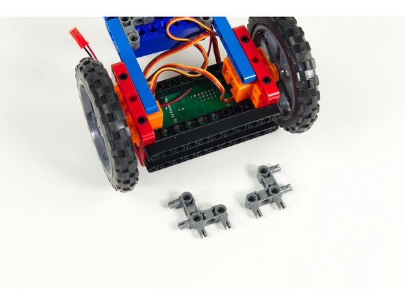
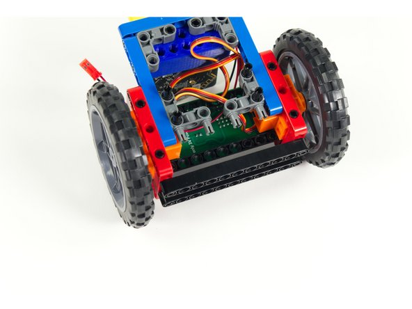
Gather the parts needed to add the Line Following Bar.
-
The Line Following Bar should be preassembled and consists of two pieces of acrylic with two IR sensors attached using 3mm bolts.
-
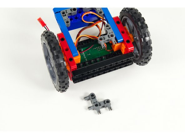
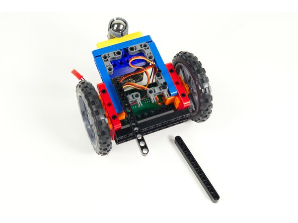
You'll need two gray 90 degree connectors, two black 11 beams, and 6 short black pins.
-
You will also need 6 F/F Jumper Wires to attach the Line Following Bar to the Bit Board.
-
-
-
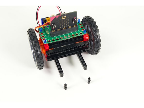
Turn the Rover upside down. We'll add two 90 degree connectors to the blue rear stabilizer beams as show.
-
-
-
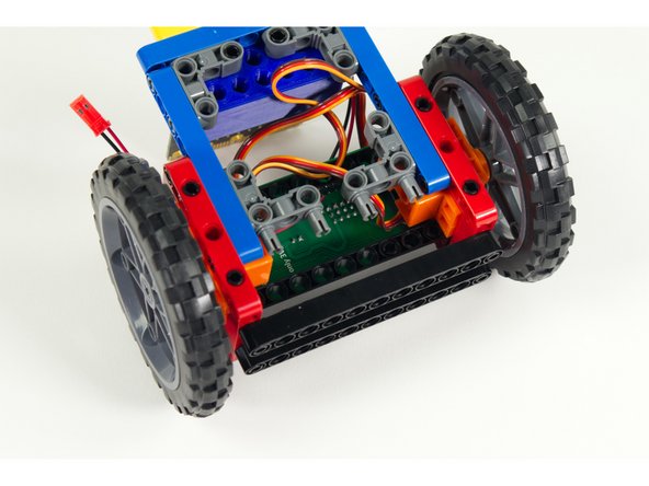
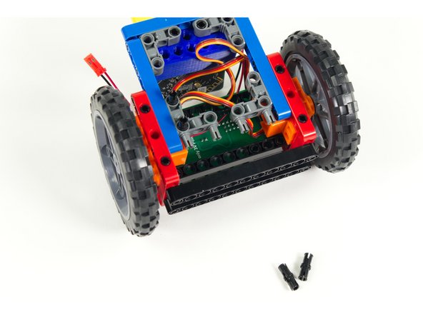
Add four short pins to the 90 degree connectors as shown, two for each connector, in line with the blue beams.
-
-
-
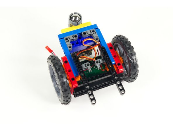
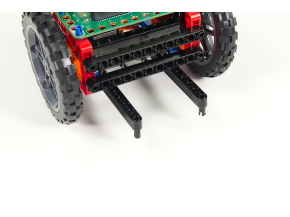
Add the black 11 beams to each set of of pins so the beams stick out the front of the Rover.
-
-
-
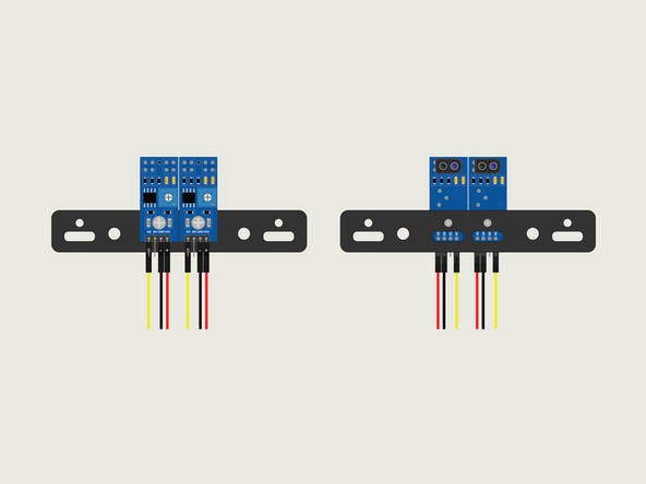
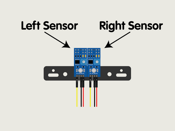
In the next step we'll be adding wires to the sensors. This step will help clarify how they are connected.
-
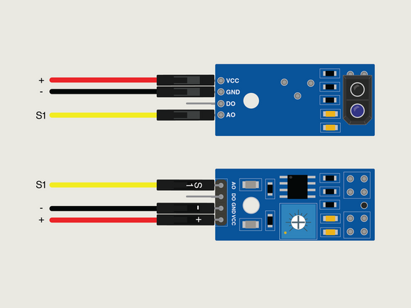
Because the sensors are already mounted it may be a challenge to read the text on them, so use this step to determine orientation and wire connections.
-
Note: Take care when connecting the wires. Accidentally mixing up VCC and GND can damage the sensor!
-
-
-
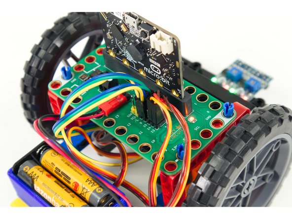
Now let's add one Crazy Circuits Ribbon Cable to each of the sensors. We'll be plugging in the end with the four independent connectors.
-
Plug + (red) into VCC; - (black) into GND, and S1 (yellow) into AO.
-
S2 (orange) does not plug into anything, but if you don't want it dangling you can plug it into DO.
-
The S1 (yellow) wire on each ribbon cable carries the data/signal from each sensor and will plug into either Pin 0 or Pin 1 on the Bit Board. (We'll do that in Step 11.)
-
AO versus DO? You'll notice we connect to the sensor pin marked AO. This is the Analog Output. The DO pin is the Digital Output.
-
While the DO can be adjusted using the small potentiometer on the sensor we've found that using the AO allows us to do calibration in the code, and gives us more control.
-
Once all the wires are connected you can move on.
-
-
-
Turn the Rover back over so it can rest of the wheels.
-
Add two short black pins to the first holes in the beams that were added in Step 5.
-
-
-
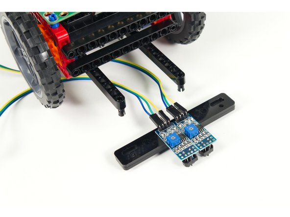
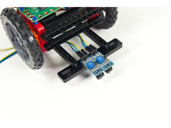
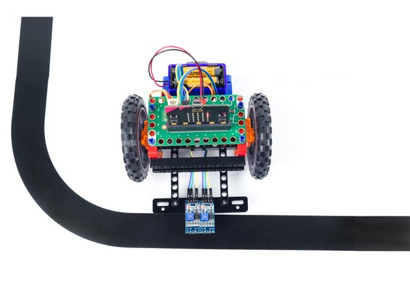
Attach the Line Following Bar to the pins we added to the beams.
-
Make sure the sensors are pointing down.
-
-
-
We'll need to route the wires from the sensors to the Bit Board.
-
We routed ours beneath the Rover so they can come up to the back of the Bit Board where they will plug in.
-
-
-
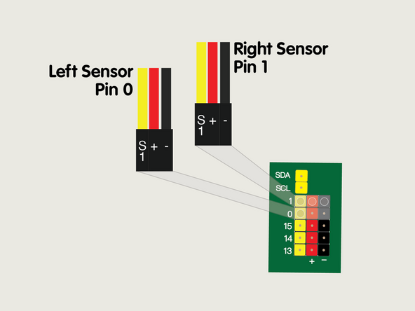
When looking at the Rover from above with it facing the same direction as you are (meaning, away from you, not facing you) you'll see the Left Sensor and the Right Sensor.
-
Each of the three wires from each sensor needs to connect to a pin on the Bit Board. This is simple to do using the Crazy Circuits Ribbon Cables since you just need to plug in the three-wire connector.
-
Plug the three-wire connector from the Left Sensor into the Pin 0 Row. The wire colors should match the pin header colors, with S1 (yellow) going to the yellow pin.
-
Plug the three-wire connector from the Right Sensor into the Pin 1 Row. The wire colors should match the pin header colors, with S1 (yellow) going to the yellow pin.
-
-
-
If you've never used a micro:bit before you'll want to check out this guide: Bit Board V2 Setup and Use
-
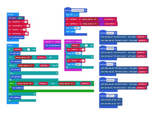
We're going to load the following code for our Rover Line Following program: https://makecode.microbit.org/_ExUPXV5yw...
-
Once the code is loaded your Rover is (almost) ready to follow a line. We'll just need to calibrate it.
-
-
-
Plug in the battery pack so your Rover has power. It will not start moving yet...
-
Place the Rover on the mat so the sensors are directly over the black line...
-
Press the A button on the micro:bit
-
You will see a smiley face on the LED matrix of the micro:bit, and then it will disappear. Your sensors are now calibrated!
-
-
-
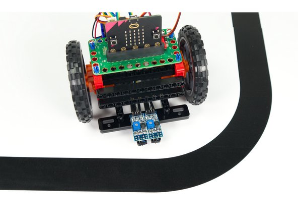
You are now ready to test out the Rover's line following capabilities.
-
Put the Rover on the mat so the sensors are over the black line, and the Rover is positioned to follow the line...
-
Press the B button and the Rover should start moving!
-
You can press the B button again to stop the Rover. It is programmed to toggle between moving and stopped.
-
Did the Rover follow the line? If not, Check the previous steps of this guide to make sure you didn't miss anything in the build, wiring, or programming.
-
-
-
Let's make a change and see how it affects the Rover's performance.
-
Turn the Rover over again and moved the two black 11 beams back further so the sensors are closer to the body of the Rover.
-
Now test it out and see how moving the sensors affects the performance. It is better or worse? Try different positions and see what results you get.
-
-
-
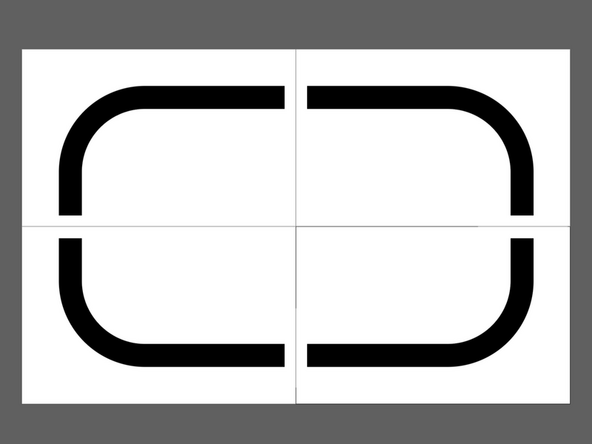
Download the file Line Following Mat Ledger.pdf at the bottom of this page in the Attached Documents section.
-
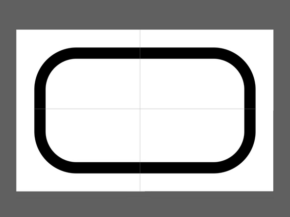
Print the four pages on Ledger/Tabloid paper and then assemble into a loop.
-
If your printer cannot print to the edge of the paper and leaves a white border just trim it off enough to allow the black lines to line up and then tape the pieces together.
-
If you prefer to make your own mat we recommend making the black line about 35mm wide (1-1/4") and it's best to avoid shiny material like electrical tape.
-


Attached Documents
