
Introduction
Note: This kit has been replaced with a newer version. Check out the Solar USB Charger 2.0 Kit.
Build a basic Solar USB charger in 15-25 minutes with this simple soldering kit.
The printable PDF has updated directions to reflect the new USB circuit that we're using.
Featured Document
-
-
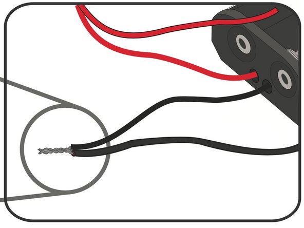
Strip the ends of all wires, including the Battery Holder.
-
-
-
Solder the Diode to the (+) Positive solder point on the Solar Cell.
-
Note: The Diode has a black bar on it. That side is soldered to the Red wire and the non black bar side is soldered to the Solar Cell.
-
Twist one end of your Red wire around the other side of the Diode. Solder into place.
-
Snip off excess parts of the Diode legs.
-
-
-
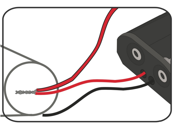
Twist the Red wire from the Solar Cell together with the Red wire from the Battery Holder.
-
-
-
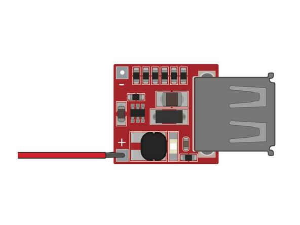
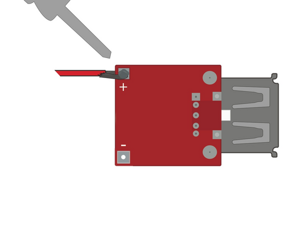
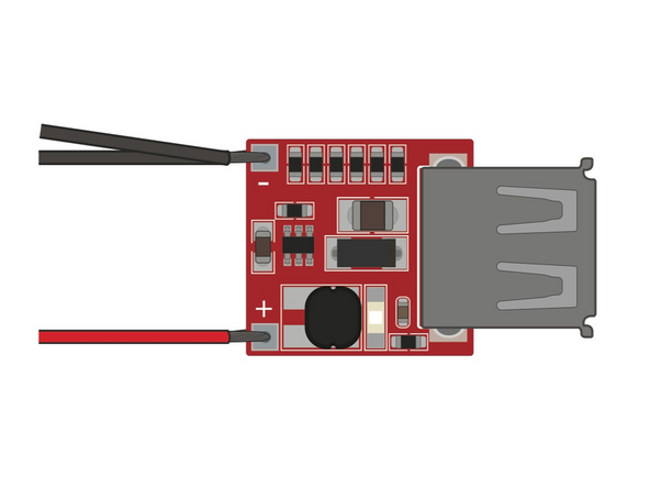
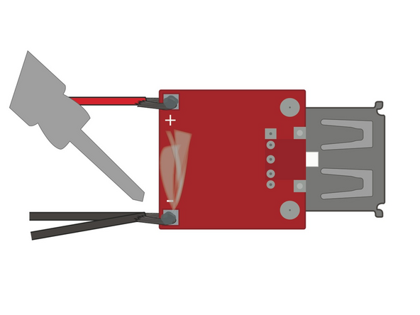
Solder the Red wire coming off the switch to the (+) Positive terminal on the USB Circuit.
-
-
-
Solder your Black wire to the (-) Negative side of the Solar Cell.
-
-
-
Twist the Black wire from the Solar Cell together with the Black Wire from the Battery Holder.
-
-
-
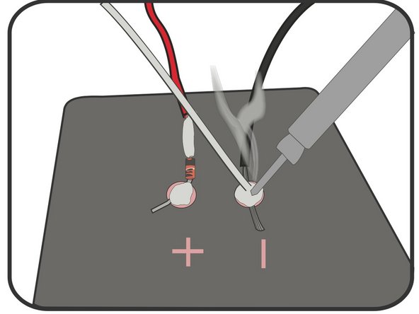
Solder the two Black wires to the (-) Negative terminal on the USB Circuit.
-
-
-
The rechargeable AA Batteries used in the kit may be dead, charge them up quickly with a wall AA charger.
-
In a pinch, use regular AA Batteries for a quick test. NEVER try to charge regular AA Batteries.
-
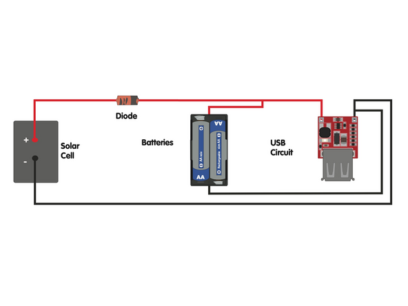
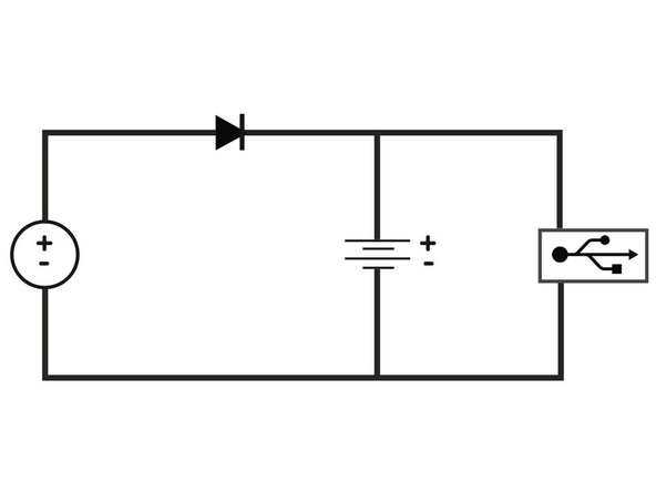
Check out the diagrams in this step if you're worried you missed something.
-
When in doubt, try a different USB device.
-
-
-
While an Altoids tin works well, it is metal and conductive.
-
Using a Dollar Store plastic food container or cheap wooden box is always a good solution.
-


Attached Documents
