Introduction
Build this Telegraph-style Key Switch with LEGO and Maker Tape!
You can use it for any circuit that needs a switch, and it works great with our Crazy Circuits parts including the Bit Board with micro:bit
Video Overview
-
-
A Telegraph Key is used for sending Morse code, and it's sometimes called a Morse Key. This isn’t exactly a Telegraph Key but the design is similar enough that we’re going to call it that.
-
We were inspired to build our version after seeing the one that Martine Segers built.
-
-
-
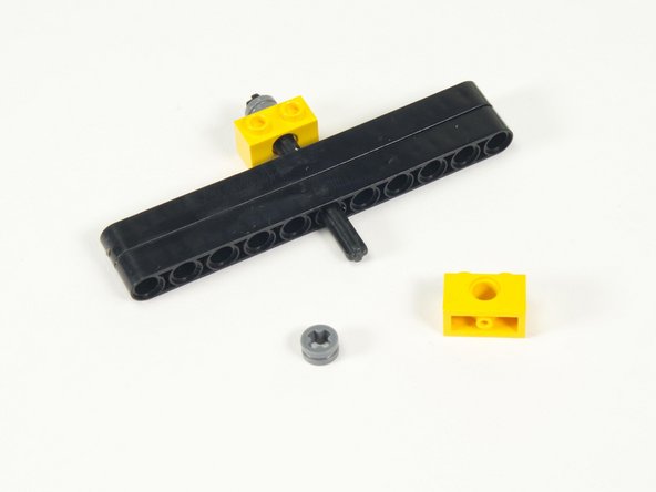
We’re going to use a few specific LEGO parts, but we’ll also highlight some alternate parts you can use.
-
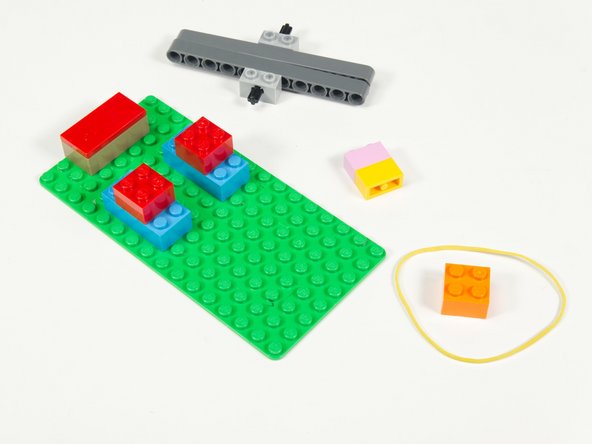
Besides the normal bricks and baseplate we’re using the following parts:
-
-
-
-
-
1 x Rubber Band
-
-
-
If you don’t have any 1 x 2 bricks with axle holes you can instead use two LEGO Brick 1 x 2 with Hole (3700).
-
You’ll also need some bushings to hold the axle in place. You can use the LEGO Half Bushing (32123 / 42136) or LEGO Technic Bush 1/2 with Teeth Type 1 (4265) or LEGO Technic Bush 1/2 with Teeth Type 2 (4265).
-
-
-
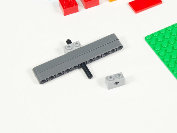
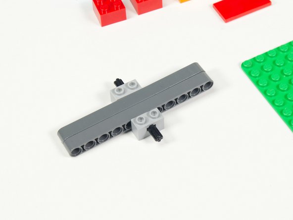
We'll start by creating the lever.
-
Place the axle through the two beams at the center with the two 1 x 2 bricks with axle holes on either side.
-
-
-
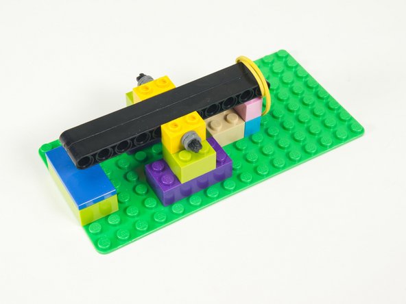
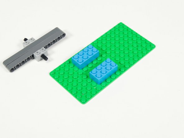
Add two 2 x 4 bricks to a baseplate. (If using a small baseplate make note of the position so you can fit the whole mechanism.)
-
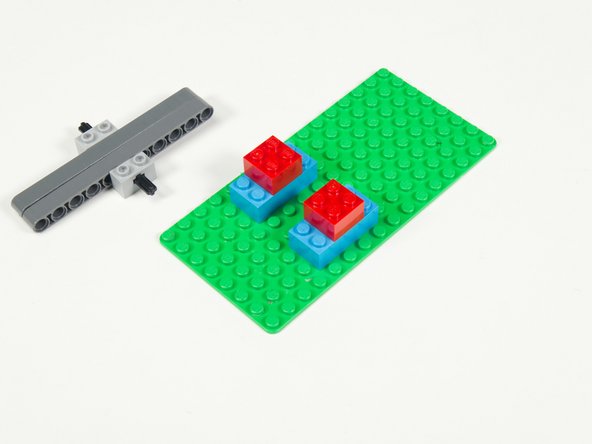
Add two 2 x 2 bricks centered on top of the 2 x 4 bricks.
-
This will serve as the support platform for the lever mechanism we've already assembled.
-
-
-
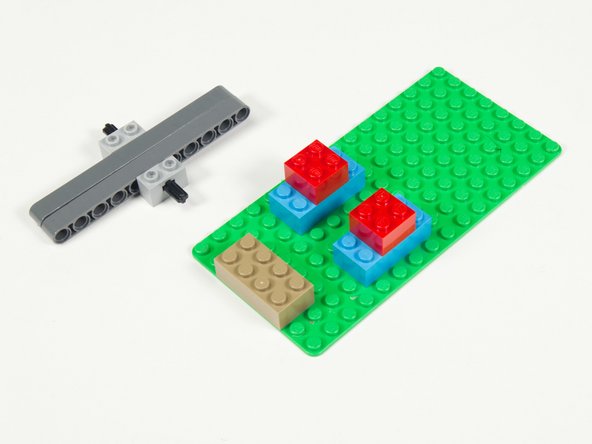
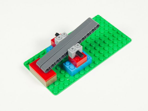
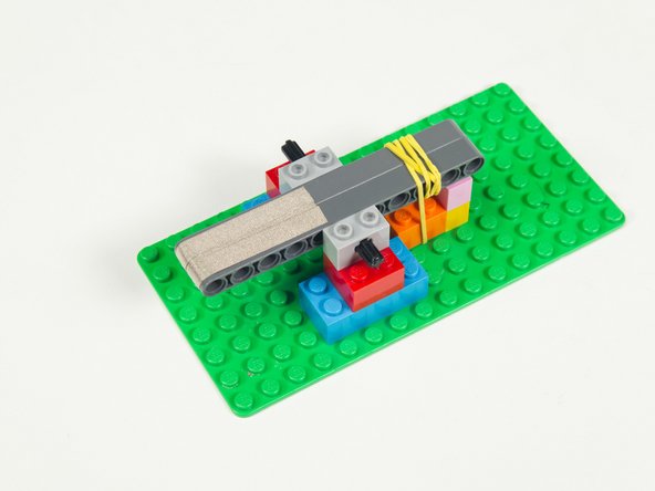
Add a 2 x 4 brick to the baseplate.
-
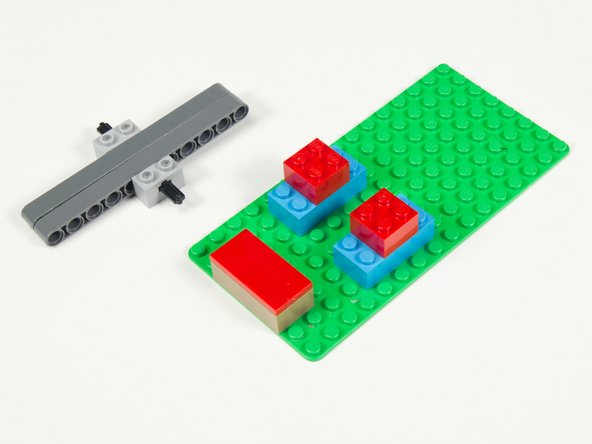
And then add a 2 x 4 flat tile on top of it.
-
Check the positioning by placing the lever mechanism on the support bricks.
-
The beams should touch the center of the flat tile.
-
-
-
Add two 1 x 2 bricks beneath the opposite end of the lever.
-
Check that the beams of the lever touch down on top of the Stopper Bricks.
-
-
-
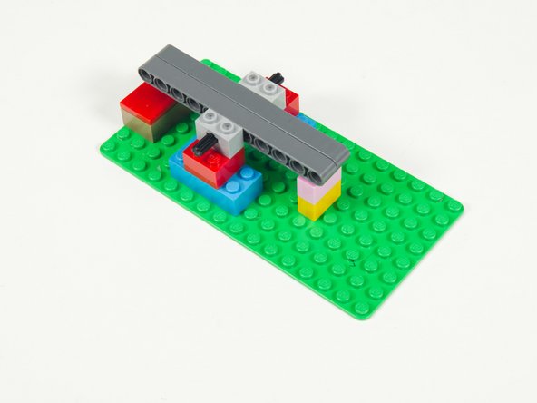
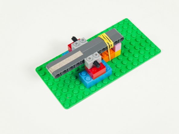
We're going to temporarily remove the lever mechanism and the Stopper Bricks we added in the previous step.
-
We'll add them back after we add the rubber band.
-
-
-
Next we'll use our Rubber Band and a 2 x 2 brick to create our spring mechanism.
-
Place the rubber band under the brick and then stick the brick down to the baseplate.
-
Add the lever mechanism back in place.
-
-
-
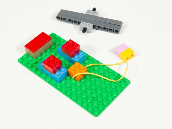
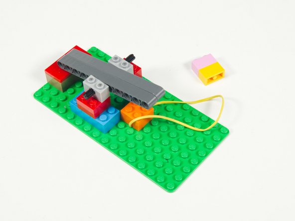
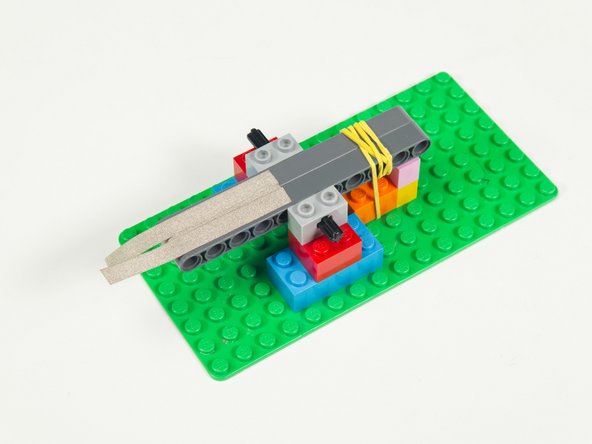
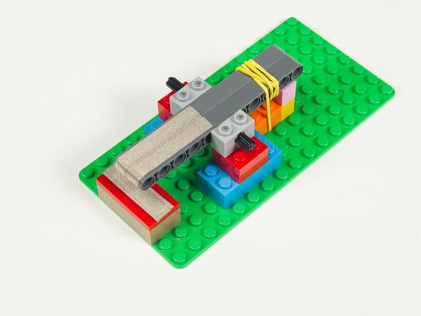
Wrap the Rubber Band around the beams so they get pulled down towards the brick.
-
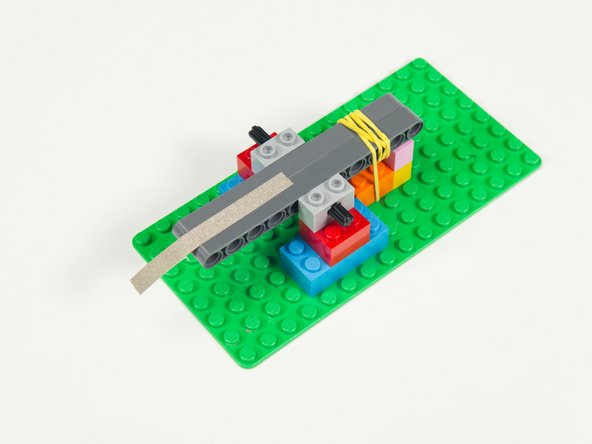
Add the Stopper Bricks back into place and test the lever movement.
-
-
-
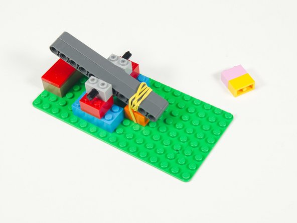
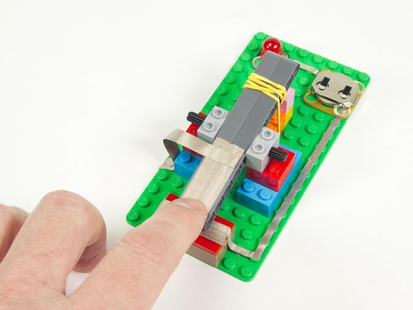
With the full assembly complete you should be able to test the action of the lever.
-
Do you get a good satisfying "click!" when pressed down? Does the lever spring back into place when released?
-
If it's all good then we're ready to add conductivity to our switch.
-
-
-
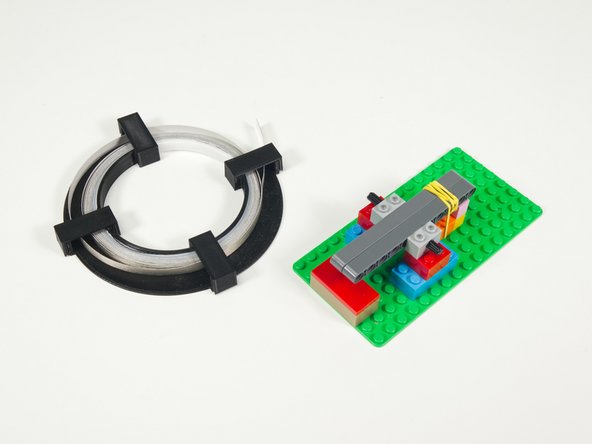
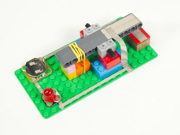
Grab that roll of 1/4" Maker Tape!
-
Remove the Contact Brick (the one with the flat tile) and add Maker Tape to it.
-
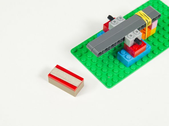
Add a few pieces across the top as shown.
-
Layering a few pieces right in the center will help the lever make better contact when pressed down.
-
-
-
Add a strip of Maker Tape down the center of the beams so it holds them together.
-
Leave enough at the end so it can wrap underneath at least 1.5 centimeters.
-
Reminder: If you cut a piece that is too short you can just add another piece and layer it on top. Maker Tape is conductive on the top and the bottom!
-
-
-
Add two more strips of Maker Tape, again leaving enough at the end to wrap around to the bottom of the beams.
-
-
-
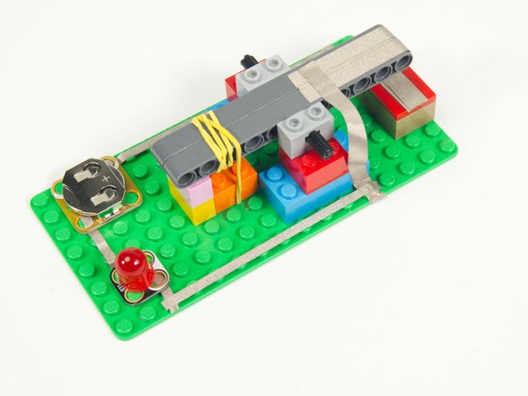
With the Maker Tape applied you can put the Contact Brick back in place.
-
-
-
Our switch is almost ready to use! We just need to add the electrical connections so we can use it in a circuit.
-
We'll build a simple circuit with a Battery and an LED for our switch to control.
-
-
-
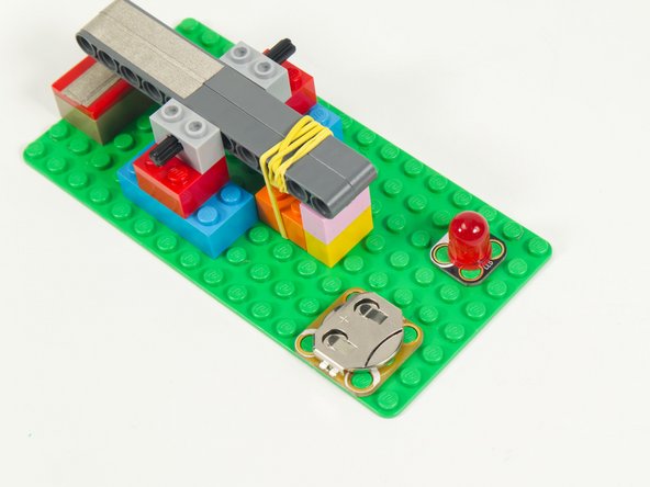
We've got just enough room on our small baseplate to fit a Crazy Circuits Battery Holder and LED.
-
-
-
Run a piece of 1/8" Maker Tape from the Contact Brick of the switch to the Negative side of the Battery Holder.
-
-
-
Add a piece of Maker Tape between the Positive side of the Battery Holder and the Positive side of the LED.
-
Make sure your parts are aligned properly! The white rings around the holes on the Crazy Circuits parts indicate Negative (or Ground).
-
-
-
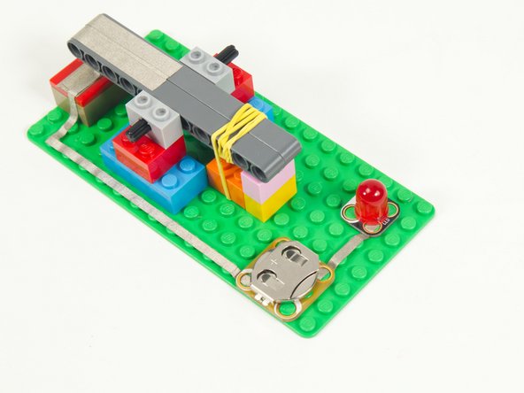
In Step 18 we added Maker Tape that connected to the Contact Brick, so now we need to add Maker Tape that will connect to the lever side of the switch.
-
Maker Tape is flexible (a great quality) so we'll use a strip that runs from the Maker Tape on the top of the lever beams down to the baseplate.
-
Make sure there's some slack so the lever can still move freely.
-
If you have issues with the middle of the Maker Tape sticking to anything you can always use a piece with most of the backing still in place.
-
-
-
The final connection! We just need to add some 1/8" Maker Tape to connect the Negative side of the LED to the 1/4" Maker Tape we added in the previous step.
-
-
-
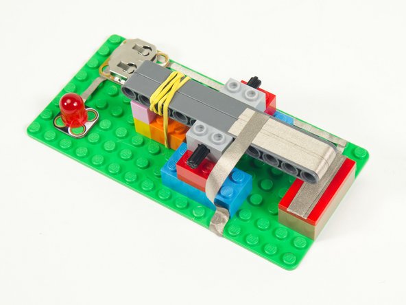
With our circuit complete, it's ready for testing!
-
Press that lever down! Did the LED light up? If not, recheck the previous steps to make sure you didn't miss anything.
-
Make sure you're using a fresh battery as well!
-
-
-
We connected our Telegraph Switch to our Bit Board and programmed the micro:bit to make beeps... Yes, it's Morse Code!
-
What else could you use this lever switch for? Perhaps a piano with multiple keys/switches/notes?
-
Make something awesome with your switch!
-