Introduction
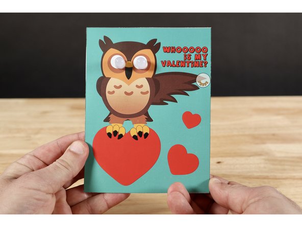
Use one of the two templates provided at the bottom of this guide to make your Valentine this fun, interactive, light-up card!
Featured Document
-
-
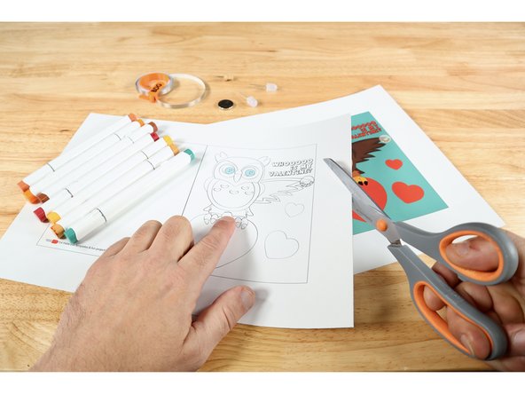
Print, select, and cut out the template you wish to work on. There's an uncolored one that you can color any way you choose. There's also a version that is already colored.
-
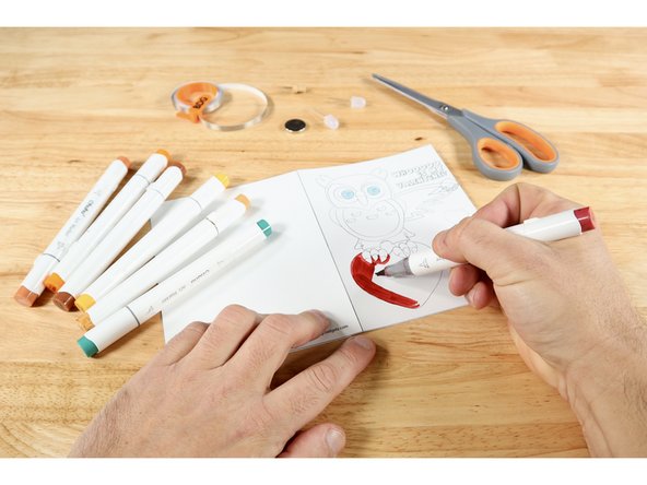
If you chose the uncolored version, now is a good time for you to use colored pencils, markers or crayons to make the cover and lettering inside look how you want it.
-
Fold the project on the dotted line so the owl becomes the cover.
-
-
-
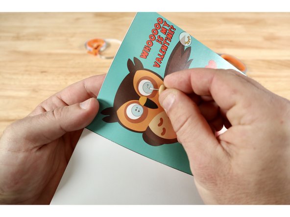
Use a push pin to poke two small holes where indicated within each of the graphics for LEDs. There will be four holes total.
-
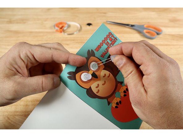
From the cover side: Thread the legs of each LED through a pair of vertically oriented holes. Note: Orientation of the legs matters! The longer Positive (+) Legs should go through the UPPER holes while the shorter Negative (-) Legs should go through the lower holes.
-
On the circuit side, fold the legs flat against the paper; away from one another as indicated on the diagram.
-
-
-
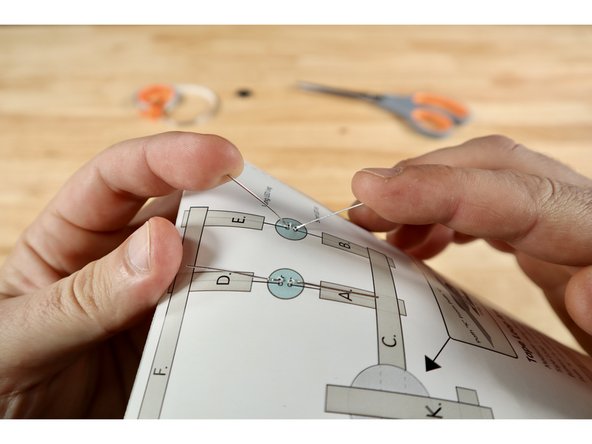
Measure, cut, peel, and stick Maker Tape paths in alphabetical order from "A-I" where shown on the diagram.
-
LED leg paths "A", "B", "D", "E" should be placed on TOP of each leg.
-
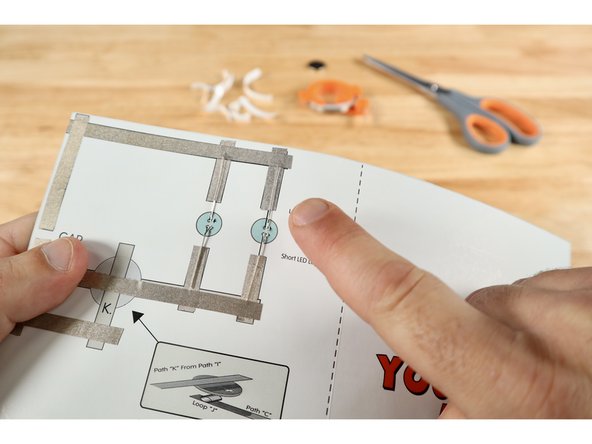
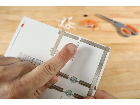
There should be an intentional gap between paths "G" and "H".
-
-
-
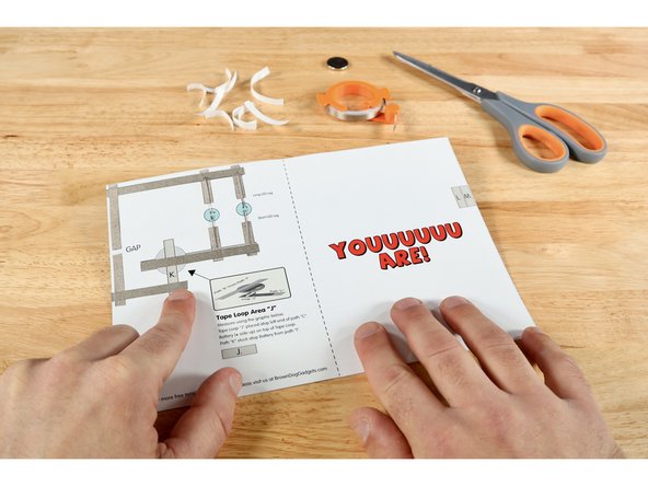
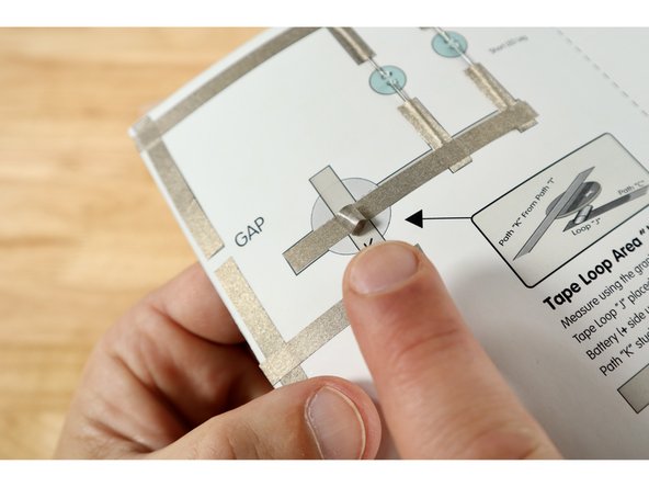
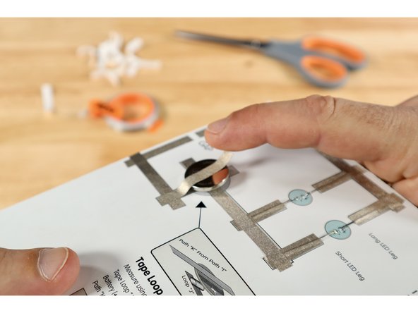
Measure, cut, and peel a piece of Maker Tape using the graphic for path "J". Use that tape to create a tape loop that is "sticky-side-out".
-
Stick that Maker Tape Loop atop path "C" somewhere within the battery graphic on the diagram.
-
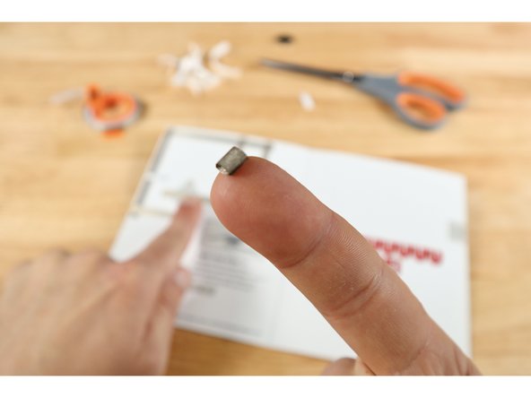
Stick the battery atop the tape loop with the Positive (+) Side facing UP.
-
Measure, cut, peel, and stick path "K" so that it makes contact with path "I" and the top of the battery.
-
-
-
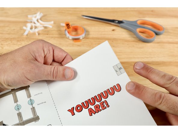
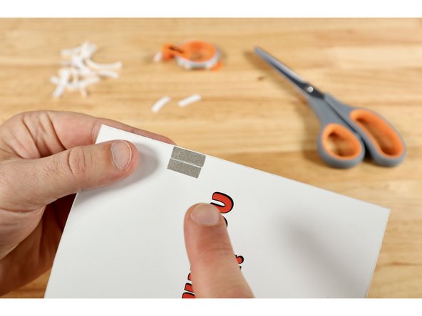
Measure, cut, peel, and stick paths "L" and "M" located on the right margin of the message panel of the card.
-
When the card is closed and the wing is pinched or pressed where indicated, the gap on the circuit side will be bridged by these two paths. Electric current will flow; lighting up the eyes for as long as these two parts are held in contact.
-
-
-
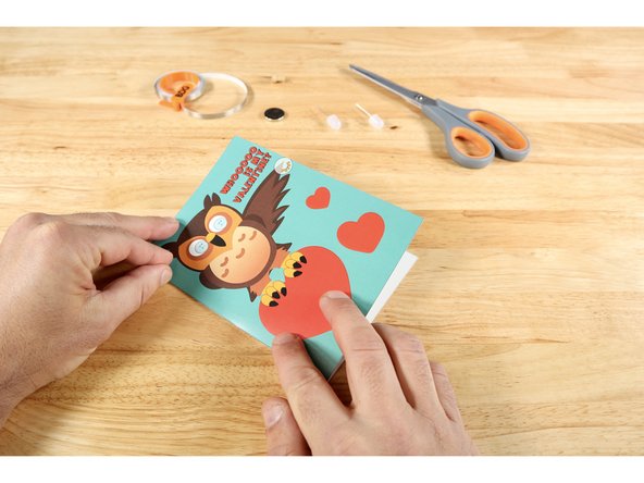
Your card is complete!
-
Remember: This card is designed so that the eyes ONLY light up when both layers of the card are pinched at the wing tip as shown.
-
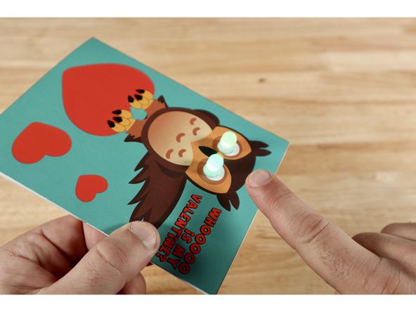


Two LEDs?! You must really love your Valentine! Tell them to give the wing a squeeze and watch those owl eyes light UP!
Two LEDs?! You must really love your Valentine! Tell them to give the wing a squeeze and watch those owl eyes light UP!