
Introduction
Use a micro:bit to build a Binary Math Game with a 4 bit register and challenge yourself to some math!
Video Overview
-
-
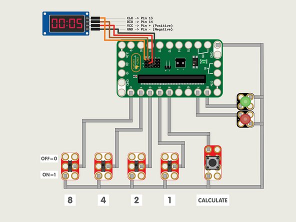
We're going to build our circuit on a large LEGO baseplate. We'll need enough room for the Bit Board, 4 switches, one button, two LEDs, and the 7 Segment Display.
-
Connect the four switches and the button as shown. Each needs to be connected to ground (GND) and to the appropriate pin.
-
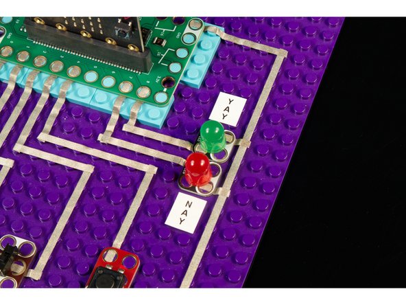
Add the LEDs. We used a red one for Pin 7, and a green one for Pin 8. They'll also need to connect to ground (GND).
-
If you like this project check out our Binary Calculator guide!
-
-
-
Using Female/Female jumper wires connect the 7 Segment Display to the pins on the back of the Bit Board.
-
You can use whatever wire colors you like, but typically we try to use red for positive, black or green for negative (ground) and colors like orange, yellow, blue, brown, etc. for "signal" wires.
-
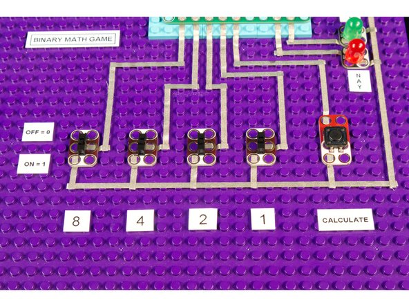
You can position the components closer or farther apart, as long as you have space to run the Maker Tape to make all the connections.
-
Make sure each path of tape from a component to the Bit Board does not cross over another path. That would cause a short circuit!
-
Remember, Maker Tape is conductive on both sides, so if you cut a piece too short you can just stick another piece on top of it to continue your circuit.
-
-
-
For our Binary Calculator we used some LEGO bricks and a rubber band to attach the 7 Segment Display, and it worked great! But for this version we used a 3D printed mount.
-
If you've got a 3D printer available check out our 7 Segment Display Holder and our other 3D Printed Parts.
-
We also used one of our 3D printed 2AAA Battery Holders. ( You can always just use some tape to attach the battery pack though.)
-
-
-
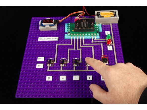
This step is completely optional, but sometimes labels are helpful.
-
Is the first switch 8 or is it 1? Is the switch on when it's up or down? With a few labels you won't have to remember! :)
-
And, yeah... we added a YAY and NAY to our green and red LEDs in case we needed a reminder which was right and which was wrong.
-
-
-
Connect a USB cable to the micro:bit and then plug it into your computer.
-
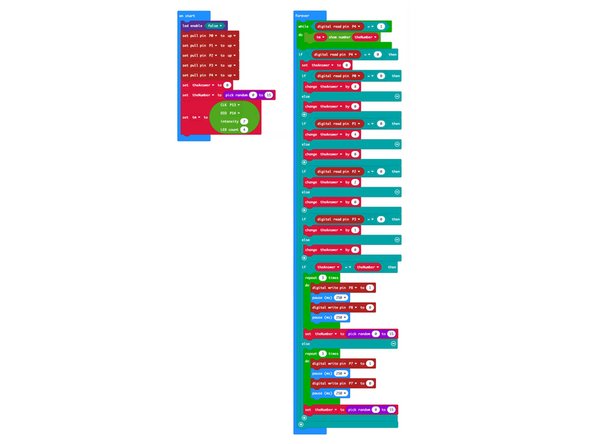
We'll be using makecode.microbit.org to program our board. It uses a simple drag and drop block interface.
-
We're going to load the following code for our Binary Math Game program: https://makecode.microbit.org/_7b4LiRVJ3...
-
-
-
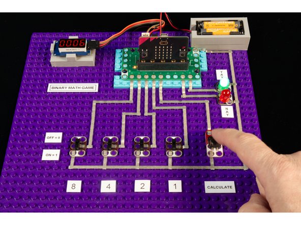
Once you've got the code loaded on the micro:bit you can test it out.
-
For this project you can either power the Bit Board using a 2 AAA battery pack, or by keeping the USB cable plugged directly into the micro:bit
-
The "game" itself is very basic, as it's just a matter of doing some addition and then setting the switches into the correct position. We intentionally kept it simple so if you've already built the Binary Calculator this is an easy way to expand upon that project.
-
-
-
Can you improve upon this project? Maybe you want to add a Crazy Circuits Piezo Speaker to make a different sound depending on if you get it right or wrong? (Or you could use the built-in piezo if you have a micro:bit V2.)
-
You could add another switch (so you have a 5 bit register) and then adjust the code so it goes from 0 to 31. A bit more challenging for sure!
-
If you come up with an awesome idea, let us know! We'd love to see it.
-


Cancel: I did not complete this guide.
One other person completed this guide.
