
Introduction
Connect a Distance Sensor to a Bit Board and view the output using four LEDs.


Video Overview
Featured Document
-
-
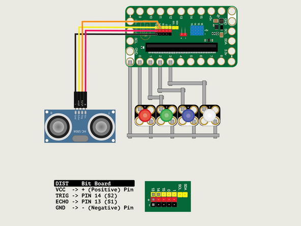
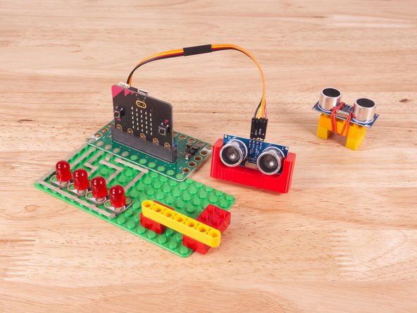
We'll connect the Distance Sensor with a Crazy Circuits Ribbon Cable using all four wires.
-
Plug the three-wire connector of the Crazy Circuits Ribbon Cable into the row with Pin 13 on the Bit Board. The wire colors should match the pin header colors, with S1 (yellow) going to the yellow pin.
-
Next, plug S2 (orange) into Pin 14. (S2 is separated from the three-wire connector to allow you to plug it into another row.)
-
Plug + (red) into VCC; S2 (orange) into TRIG; S1 (yellow) into ECHO; and - (black) into GND.
-
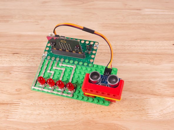
We'll use Maker Tape to connect the LEDs to the Bit Board on a LEGO baseplate.
-
Connect the Negative (-) side of each LED to a Ground (GND) hole on the Bit Board.
-
Connect the Positive (+) side of the LEDs as shown, so each LED connects to one of the following pins on the Bit Board: Pin 0, Pin 1, Pin 2, and Pin 3.
-
-
-
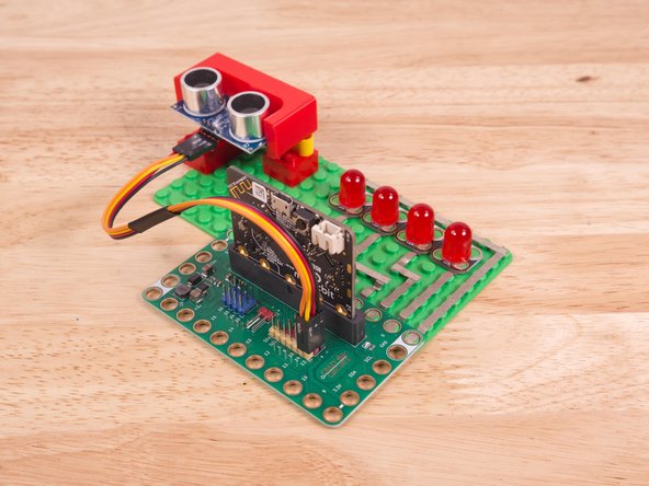
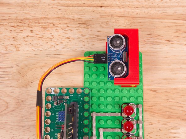
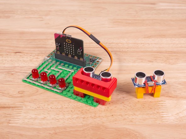
We used a 3D printed part we designed to hold the Distance Sensor in place on the LEGO baseplate.
-
A few Technic pins, a Technic beam, and some LEGO bricks are all that is needed.
-
Alternately you can use some LEGO bricks and a rubber band or tape to hold the sensor in place. (But don't use anything conductive!)
-
3D print your own Distance Sensor Holder with Holes. (It's the same one we use in our Bit Board Rover Kit).
-
-
-
If you've never used a micro:bit before you'll want to check out this guide: Bit Board V2 Setup and Use
-
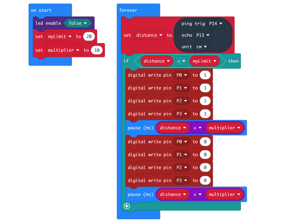
We're going to load the following code for our Distance Sensor LEDs Flashing program: https://makecode.microbit.org/_1zuVj6WM8...
-
In the forever block we'll set Pin 14 and Pin 13 to TRIG and ECHO (respectively) so we can read the Distance Sensor. This allows us to continually read the sensor and assign the value to distance.
-
We then check if the distance is lower than myLimit (which we set to 20) and if so we blink our LEDs.
-
For this version we actually use the distance (multiplied by the multiplier value) to calculate the time between the blinking of the LEDs. As we get closer to the sensor the LEDs will blink faster.
-
If the distance is greater than myLimit we do not blink the LEDs. And since the last state they were in was off the LEDs will be off.
-
-
-
Once the code is loaded it should start running immediately.
-
You can power the micro:bit via the USB cable you used to load the code or you can use a battery pack plugged into the Bit Board.
-
Move your hand (or a flat object) in front of the sensor. When you are within 20cm of the sensor the LEDs should start blinking.
-
As you get closer to the sensor rate of the LEDs flashing will increase.
-
-
-
Follow along with our recorded Live Stream!
-
You can watch the full video of us walking through this project, along with explaining and exploring the code: https://www.youtube.com/live/ZamfVb4u-f0
-
Attached Documents
