
Introduction
Connect a Distance Sensor to a Bit Board and view the output using a 7 Segment Display.

Video Overview
Featured Document
-
-
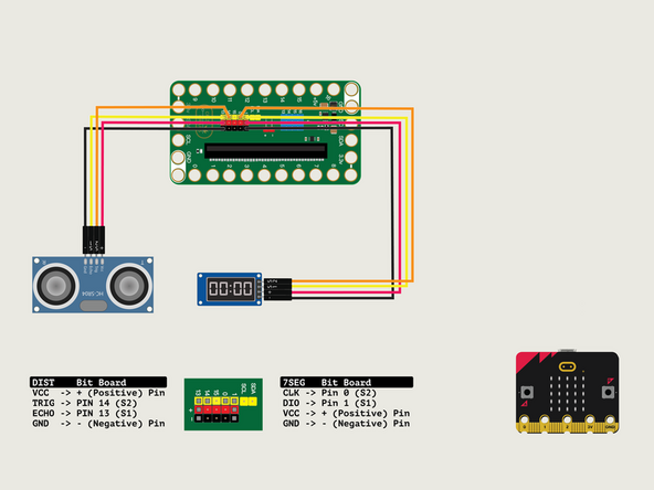
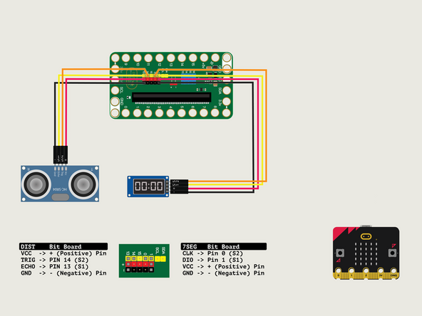
We'll connect the Distance Sensor with a Crazy Circuits Ribbon Cable using all four wires.
-
Plug the three-wire connector of the Crazy Circuits Ribbon Cable into the row with Pin 13 on the Bit Board. The wire colors should match the pin header colors, with S1 (yellow) going to the yellow pin.
-
Next, plug S2 (orange) into Pin 14. (S2 is separated from the three-wire connector to allow you to plug it into another row.)
-
To the Distance Sensor plug + (red) into VCC; S2 (orange) into TRIG; S1 (yellow) into ECHO; and - (black) into GND.
-
-
-
We'll connect the 7 Segment Display with a Crazy Circuits Ribbon Cable using all four wires.
-
Start by plugging the connector with the three wires in it (Black, Red, Yellow) into the Pin 1 row of the Bit Board. (Make sure the Black wire is in - and the Yellow wire labeled S1 is closest to the number 1 on the Bit Board.)
-
We can then plug the Orange wire labeled S2 into Pin 0 on the Bit Board.
-
Now we'll connect the other end of the Ribbon Cable to the 7 Segment Display.
-
The pin labels are on the back of the 7 Segment Display PCB. From top to bottom it's CLK, DIO, VCC, GND.
-
CLK stands for Clock and DIO stands for Data Input/Output. VCC is the Positive (+) and GND is the Ground (-) or Negative.
-
S2 (Orange) goes to CLK, S1 (Yellow) goes to DIO, and then + (Positive) goes to VCC and - (Ground or Negative) goes to GND.
-
Make sure every wire is connected in the correct place, or our display will not work!
-
-
-
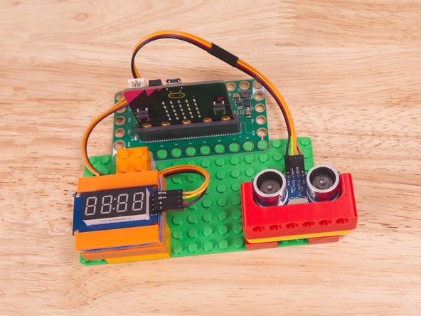
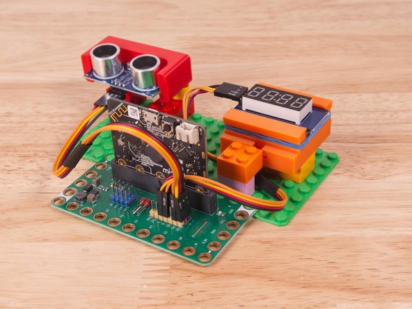
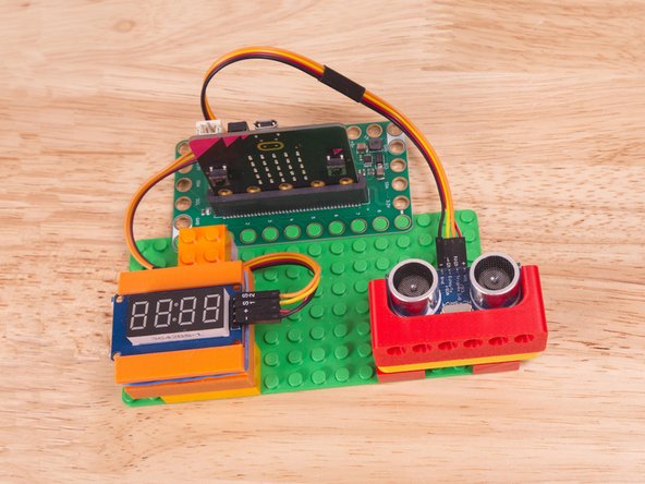
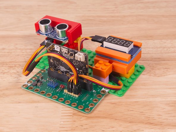
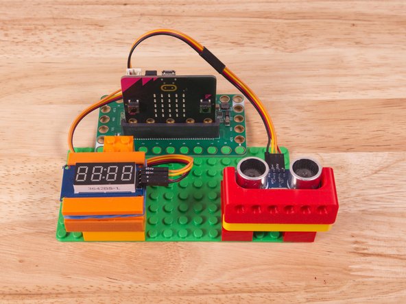
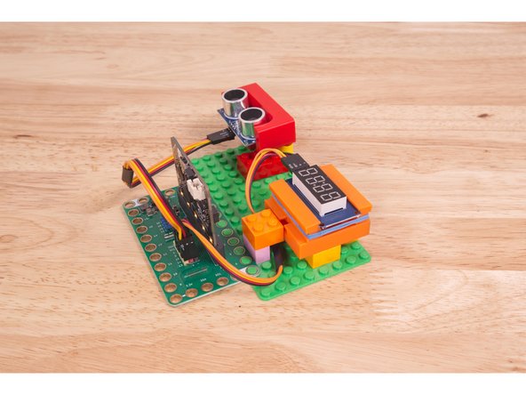
We used a 3D printed part we designed to hold the Distance Sensor in place on the LEGO baseplate.
-
A few Technic pins, a Technic beam, and some LEGO bricks are all that is needed.
-
Alternately you can use some LEGO bricks and a rubber band or tape to hold the sensor in place. (But don't use anything conductive!)
-
We also used a custom holder to hold the display in place.
-
3D print your own Distance Sensor Holder with Holes and 7 Segment Display Holder.
-
-
-
If you've never used a micro:bit before you'll want to check out this guide: Bit Board V2 Setup and Use
-
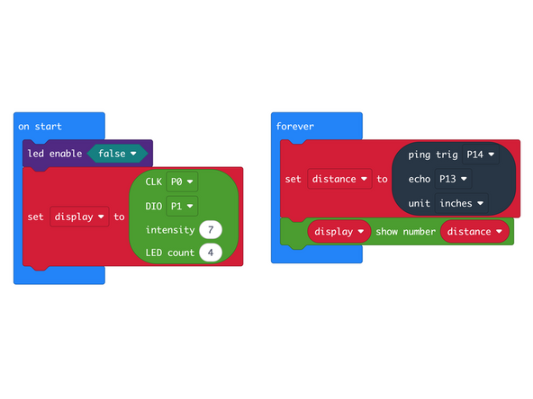
We're going to load the following code for our Display Distance Inches program: https://makecode.microbit.org/_6Y6aPoJE8...
-
In the on start block we'll set up our 7 Segment Display.
-
In our forever loop we'll assign the reading from the Distance Sensor to a variable named distance and then display the value on the 7 Segment Display.
-
In this version we've made one change from the previous version... We are now displaying the distance in Inches instead of Centimeters.
-
-
-
Once the code is loaded it should start running immediately.
-
You can power the micro:bit via the USB cable you used to load the code or you can use a battery pack plugged into the Bit Board.
-
Move your hand (or a flat object) in front of the sensor. The display will show the number changing to reflect the distance (in Inches) between the object and the sensor.
-
-
-
Follow along with our recorded Live Stream!
-
You can watch the full video of us walking through this project, along with explaining and exploring the code: https://youtube.com/live/ZXkvNJzMMh8
-
Attached Documents
