
Introduction
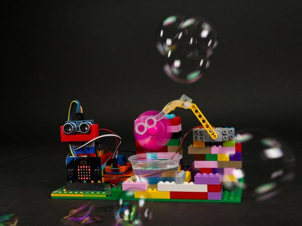
Build our classic Bubble Machine with the addition of a Distance Sensor to shoot bubbles at anyone who gets too close!
This guide is a follow-up to our Bubble Machine guide and adds a Distance Sensor to trigger the bubbles in place of a push button.
Video Overview
Featured Document
-
-
The Distance Bubble Machine is based on our original Bubble Machine but uses a Distance Sensor in place of a push button.
-
Take a look at the Bubble Machine guide to get the gist of building the LEGO portion of the project.
-
-
-
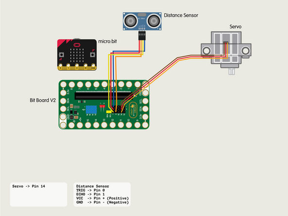
For all of the connections to the Bit Board we will be using the set of black pins for this project instead of the blue pins.
-
Plug the servo connector into the row for Pin 14. The orange wire should go to the pin closest to the 15 on the board, the red wire goes into the +5v row, and the brown wire goes into the - row, which is ground.
-
-
-
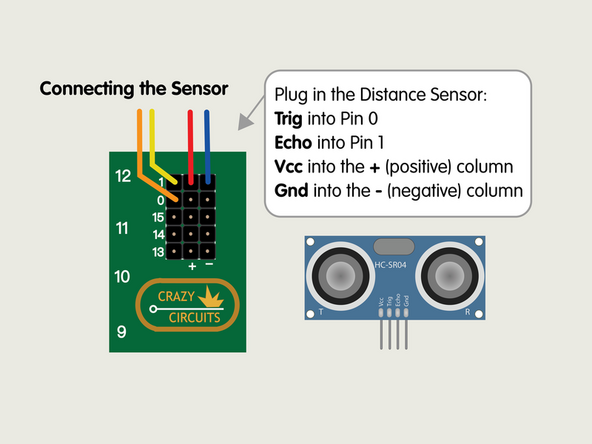
Plug in the Distance Sensor and connect the Trig pin to Pin 0, the Echo to Pin 1, and then Vcc to a pin in the + (positive) column and Gnd to a pin in the - (negative) column.
-
-
-
If you've never uses a Relay Module you may want to check out our guide first.
-
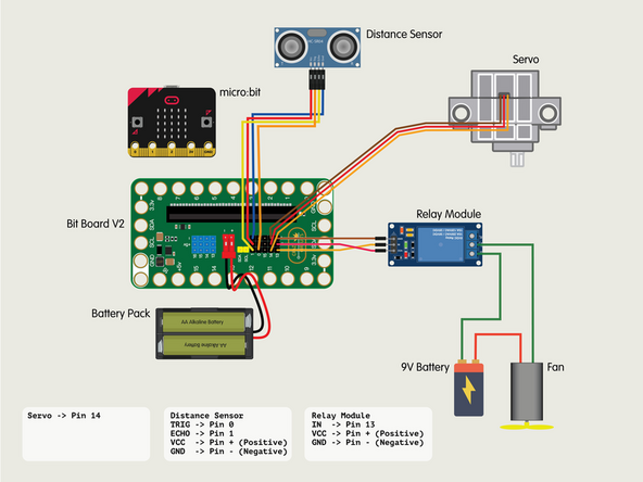
Connect the IN from the Relay Module to Pin 13.
-
Connect VCC from the Relay Module to a + (positive) pin.
-
Connect GND from the Relay Module to a - (negative or “ground”) pin.
-
-
-
Our Motor with a Fan (along with the 9 Volt Battery) will connect to the Relay to use it as a "Smart Switch" that can be controlled by the Bit Board.
-
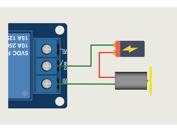
The Relay Module will have three connections on the screw terminal side.
-
COM is Common.
-
NO is Normally Open.
-
NC is for Normally Closed.
-
NO (Normally Open) is how most switches work. The circuit path is open (or not completed) when the switch is off. Turning the switch on closes the circuit path.
-
Follow the diagram to connect the Motor & Battery to the Relay inline to act as a NO switch.
-
-
-
If you've never used a micro:bit before you'll want to check out this guide: Bit Board V1 Setup and Use
-
Note that while the setup guide is for V1 most of the information is general and will apply to V2 as well.
-
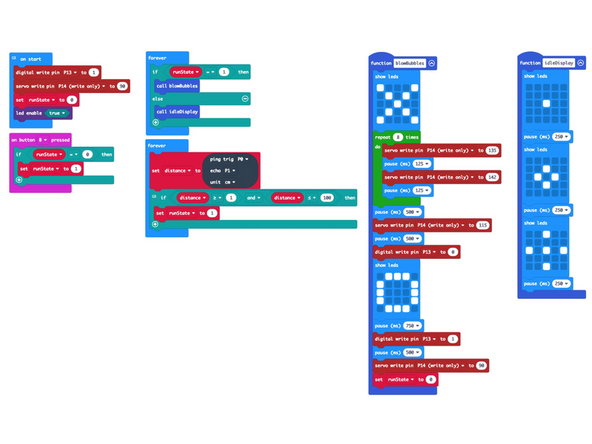
We're going to load the following code for our Distance Bubble Machine program: https://makecode.microbit.org/_Ap22Hxbam...
-
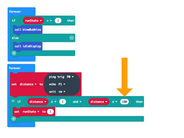
If you want to adjust the distance from the sensor that will trigger it, just change the 100 to some other value. (Any value lower than 200 should work.)
-
Note that we look for a low value equal to or greater than 1. We found that occasionally the sensor returned 0, so the 1 prevents false triggers.
-
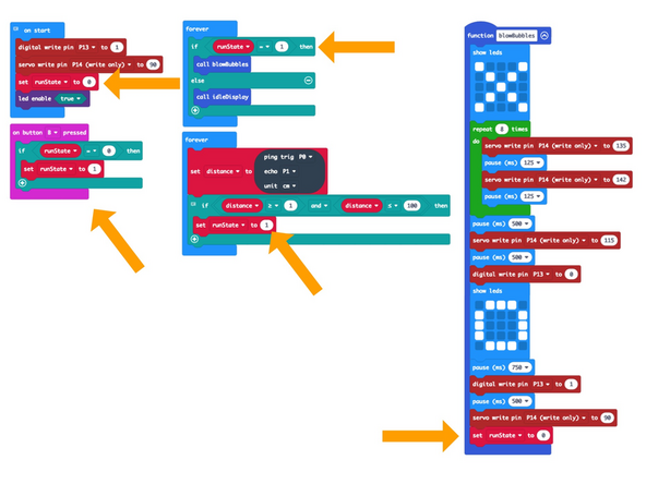
Finally we control the bubble blasting with a runState variable. This allows us to have the bubble blowing triggered by the sensor, but also when we press the B button, in case we want to stand behind the Bubble Machine and blast some bubbles at an unsuspecting victim.
-
-
-
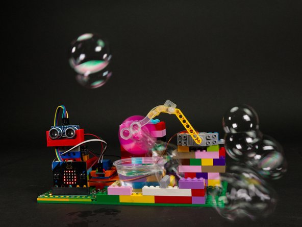
Once you've got the code loaded and bubbles in place you can test it out!
-
(Although you may want to do your first tests without bubbles!)
-
When you (or an object) get close enough to the Distance Sensor it will trigger the bubble blowing process.
-
Note: For this video we set the distance in the code to 30cm. It is normally at 100cm.
-
Did you get bubbled? Great! It's working!
-
-
-
Now that you've built a Distance Bubble Machine you're ready to do so much more!
-
You can make changes to this project, or check out some of our other fun ideas.
-
Keep On Bubbling!
-


Attached Documents
