
Introduction
Learn how a Relay Module works and how to control it using a micro:bit with our Bit Board.
Note: The Version 1 Bit Board had a small built-in relay (connected to Pin 16) that is not found on the Version 2 Bit Board. This guide will work with either version of the Bit Board.
Video Overview
Featured Document
-
-
A Relay Module is basically an electronic switch. Instead of the type of switch you would turn on and off with your finger a relay can be controlled by electricity, so you can connect a microcontroller (such as a micro:bit and a Bit Board) to control the switch using code.
-
In this guide we'll use a module with a single relay, but if you search you'll find modules with two, four, and even eight relays.
-
Most relay modules will have at least one LED that turns on when power is applied, and many (though not all) will have an LED for the relay that turns off (or on) when the relay coil is engaged.
-
We won't cover these multi-relay modules, but if you do use one, just be aware that each relay will need to be connected to (and thusly controlled by) a separate pin on the micro:bit
-
-
-
Imagine connecting a motor to a battery. It will start spinning immediately, but if you add a switch, you can control the flow of electricity and when the motor spins and does not spin.
-
Now let's imagine that your switch is actually a relay. It's still a switch but now you can control it with code.
-
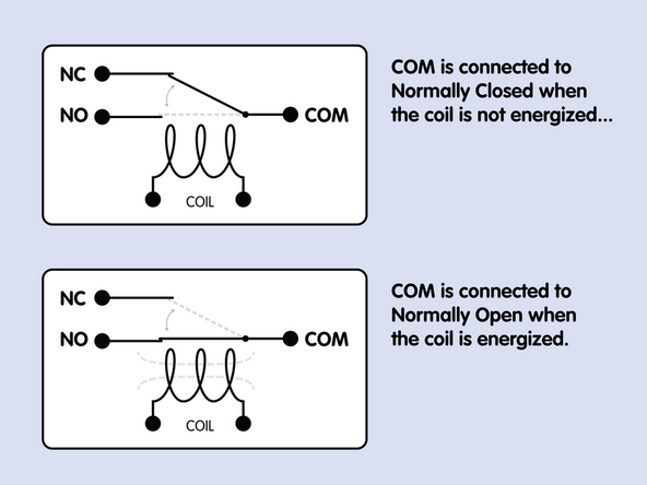
The screw terminal side of the relay shows three connectors: COM stands for Common, NO stands for Normally Open and NC stands for Normally Closed.
-
COM can electrically connect to the NO or the NC connector, depending on the signals it receives from the micro:bit
-
In our example the motor will only run when the Relay Module is enabled by Pin 13 being turned OFF in the code.
-
Yes, it seems backwards, but setting Pin 13 to 0 turns the relay ON.
-
If we had the motor connected to NC instead of NO it would always be running unless we turned off Pin 13. This is because that switch is Normally Closed.
-
-
-
Without going too deep into how a relay works, here's a diagram showing what happens!
-
There is an electromagnetic coil inside the relay, and when it is energized it pulls a tiny metal lever (the actual switch) away from the NC connector and towards the NO connector.
-
Since the relay relies on a mechanical mechanism it can wear out from use. There are also optical relays which are "solid state" and do not contain moving parts which can wear out.
-
When the relay turns on you will hear a "click" which is the sound of the lever moving from one contact to the other.
-
Fun Fact: The turn signals (or "blinkers") in cars used to use mechanical relays, which created the clicking sound you hear when the turn signal is on. In modern vehicles optical relays are used, but since they are silent an audio file of the clicking is played by the car!
-
-
-
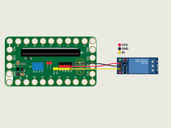
We're going to connect our Relay Module to a Bit Board V2.
-
Connect the IN from the Relay Module to Pin 13.
-
Connect GND from the Relay Module to a - (negative or “ground”) pin.
-
Connect VCC from the Relay Module to a + (positive) pin.
-
For this demo we won't connect anything to the COM, NC, or NO terminals of the Relay Module. Previous steps explain how those work in detail.
-
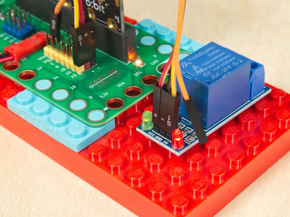
If you're using a Crazy Circuits Ribbon Cable plug the large connector into the Bit Board and let S2 (the orange wire) hang loose...
-
...then connect the other end to the Relay Module, again letting the S2 wire hang loose. Notice that the Relay Module has the GND in the center, so pay attention to the order of the pins when plugging in the wires.
-
Note! The Bit Board V2 has a set of blue connectors for Pins 13 through 16. These should not be used with a Relay Module. They are for specific sensors and servo motors. Make sure you use one of the black/red/yellow pins; 13, 14, 15, 0, or 1
-
-
-
If you've never used a micro:bit before you'll want to check out this guide: Bit Board V2 Setup and Use
-
We're going to load the following code for our Relay Test program: https://makecode.microbit.org/_dTzK5j2sL...
-
Once the code is loaded onto the micro:bit the Relay Module should start clicking on and off, every second.
-
Note! Typically when you enable (turn on) a pin you set it to 1. For the Relay Module you set the pin to 0 instead.
-
-
-
Is your Relay Module clicking on and off? If so, it works!
-
Tip: If you see the LED light up to indicate the relay has engaged, but you do not hear the clicking sound there's a chance something isn't working right.
-
-
-
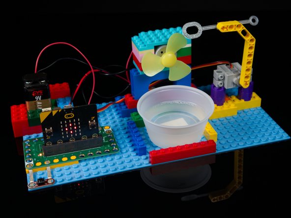
Maybe you want to build your own Bubble Machine or Plant Watering System... With a Relay Module you can do that!
-
What other ideas can you come up with for a Relay Module? Maybe you could connect a battery powered toy and use a sensor to turn it on and off. (Great prank possibilities abound!)
-
Note that while the relay may show voltage as high as 250 volts, and current as high as 15 amps, we recommend only using low voltage/current (12 volts or lower, and 1 amp or lower) in a learning environment. If you're not sure if something is safe, consult with an expert.
-


Attached Documents
