Introduction
This Omni Wheel Rover is an alternative Rover you can build by adding Omni Wheels and two more servos to our standard Rover Kit.
Depending on the Omni Wheels you purchase we may also recommend 3D printing new hubs. (See the guide: 3D Printed Parts: Omni Wheel Hub)
Video Overview
-
-
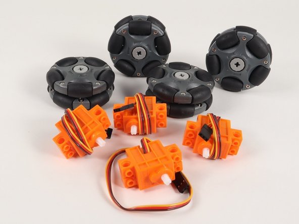
This is an Advanced Build! Besides the parts in the Rover Kit you will need two additional Continuous Rotation 360 Degree Servos and a set of four Omni Wheels.
-
What are Omni Wheels? Check out one of our previous projects, the Omni Wheel Robot, for a good primer on how Omni Wheels work.
-
The Rover Kit comes with just two servos, but if you borrow two servos from another kit, or get two more servos separately, you can build this project.
-
You will also need four Omni Wheels. We’ll detail that in Step 3.
-
-
-
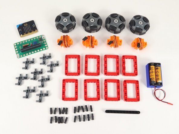
Gather the parts needed to assemble the Omni Wheel Rover.
-
You'll find most of the parts in the standard Bit Board Rover Kit but you'll need to have two additional servos and the Omni Wheels to complete this build.
-
-
-
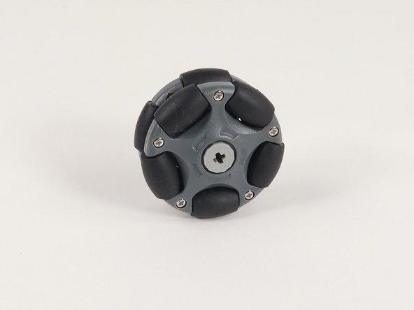
You have a few options for the Omni Wheels.
-
For our previous Omni Wheel Robot We’ve used these Vex Omni Wheels along with a 3D printed adapter we created.
-
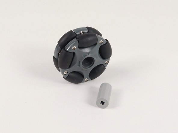
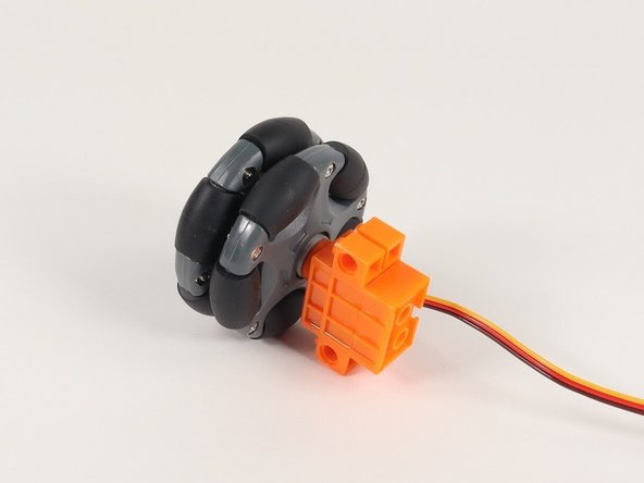
Alternately, you can use these LEGO compatible wheels, but the LEGO hub that comes with it doesn’t really work when attached to servos. (It works well for LEGO axles going all the way through and held in place, but not when put directly onto a short servo axle.)
-
We have another 3D printed hub that works well in place of the hub that is included.
-
Check out the guide and grab the files to print your own: Omni Wheel Hub
-
-
-
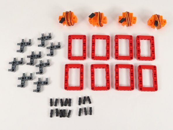
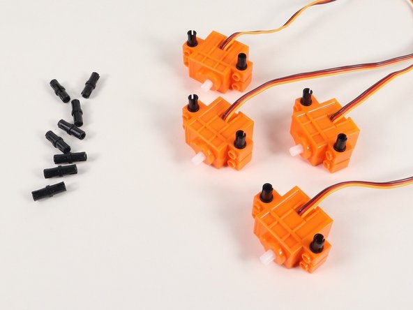
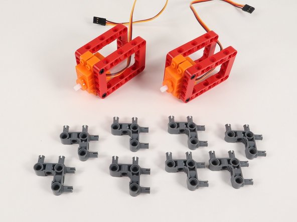
We'll start with 4 continuous rotation servos, 8 red frames, 8 gray 90° connecters, and 16 black pins.
-
-
-
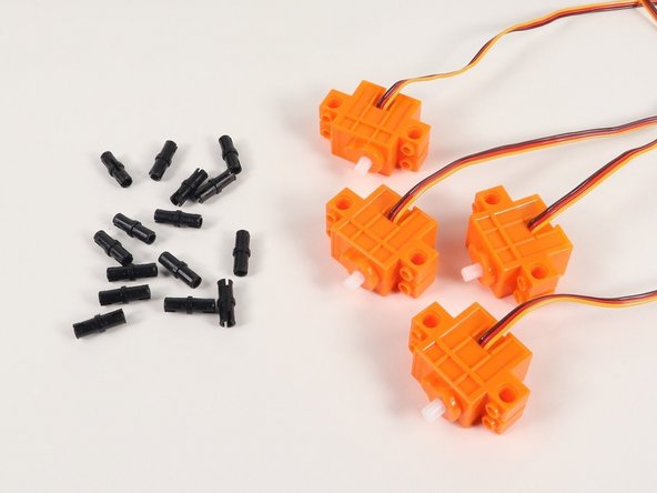
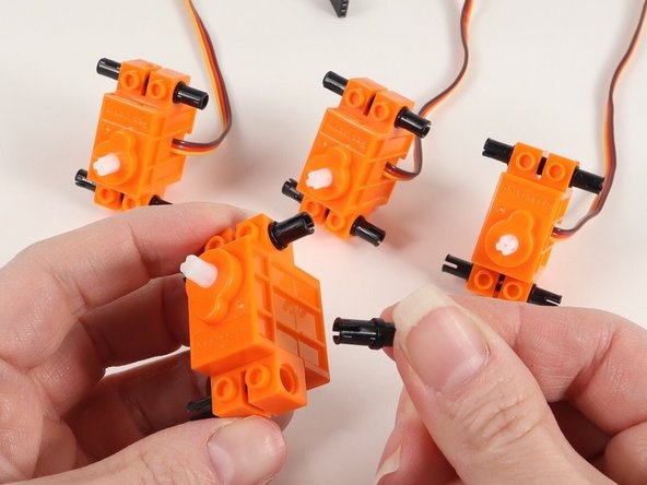
Add 4 black pins to a continuous rotation servo. You will need to do this to all 4 servos.
-
-
-
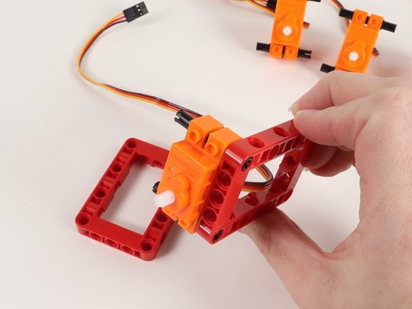
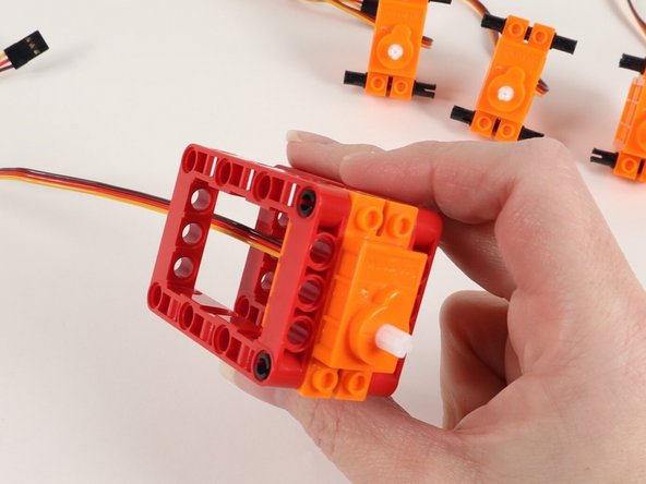
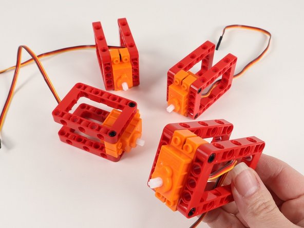
Add red frames onto each side of the servo.
-
Continue adding red frames until all 4 servos have two red frames on the black pins.
-
-
-
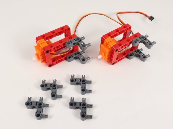
Add gray 90° connectors to the red frames as shown.
-
Assemble two sets of this build.
-
-
-
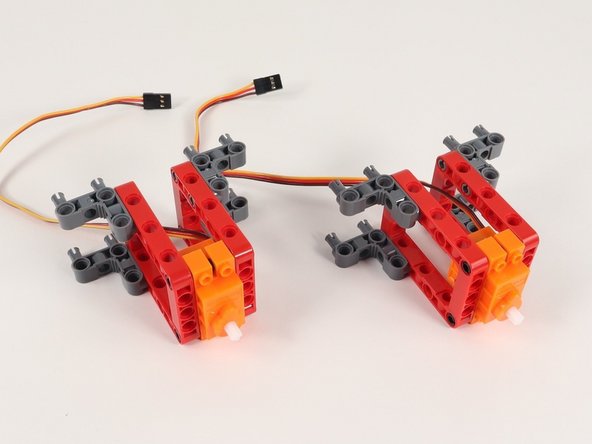
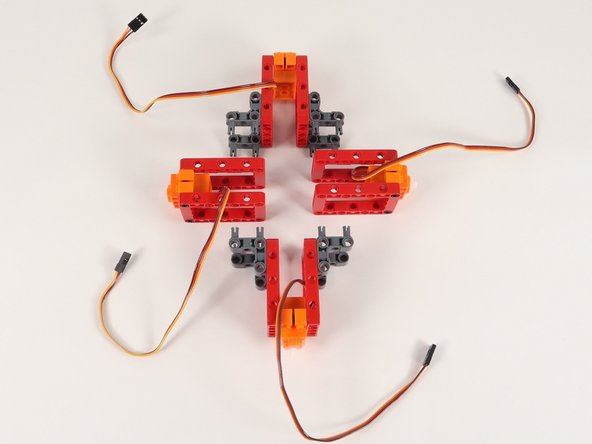
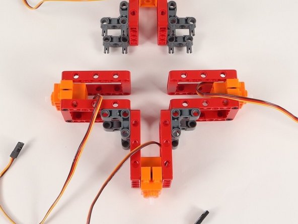
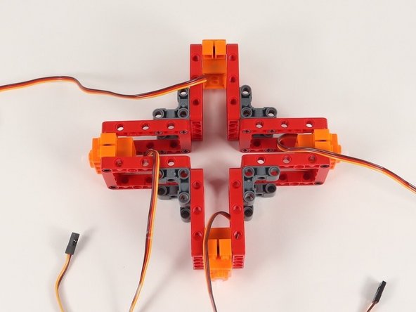
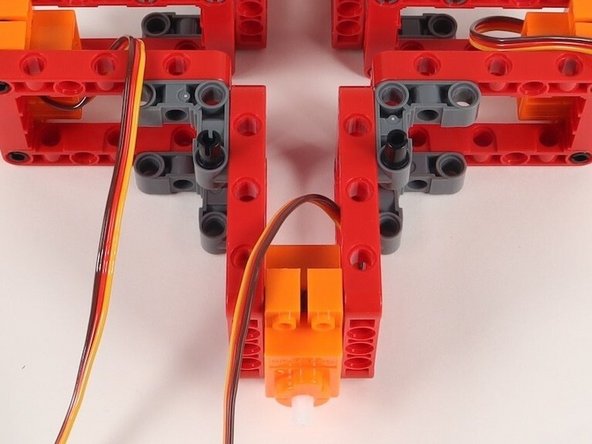
Connect the servos with 90° connectors to the frame without connector, creating a 4 sided shape with all servo shafts pointing outward.
-
When connecting the servos, make sure all servos are aligned the same way - wires all to the right of the servo and shafts toward the bottom.
-
-
-
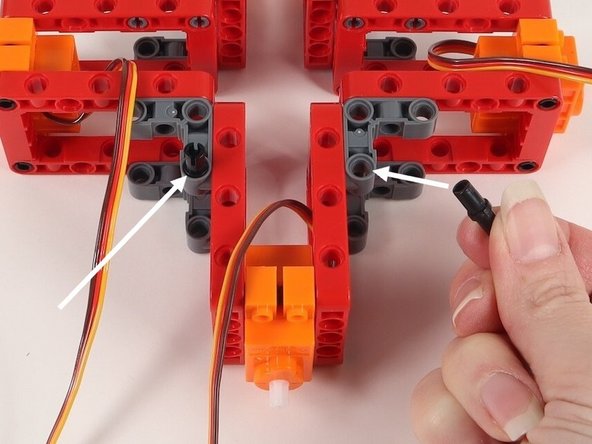
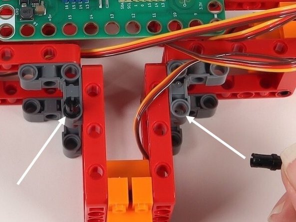
Add two black pins onto the 90° connectors on one side of the build. It does not matter at this point which side these go on since the build is symmetrical.
-
These will hold the Bit Board in place which will be added in the next step.
-
-
-
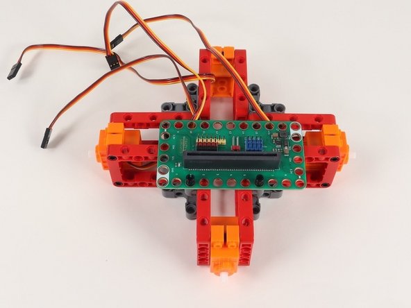
Add the Bit Board onto the black pins with pins 0-8 on the Bit Board facing you.
-
The Bit Board will not be perfectly centered due to the style of build.
-
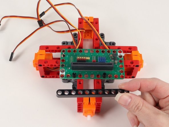
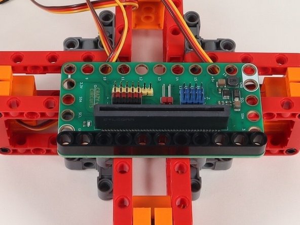
Add an 11-hole black beam onto the black pins to hold the Bit Board down.
-
-
-
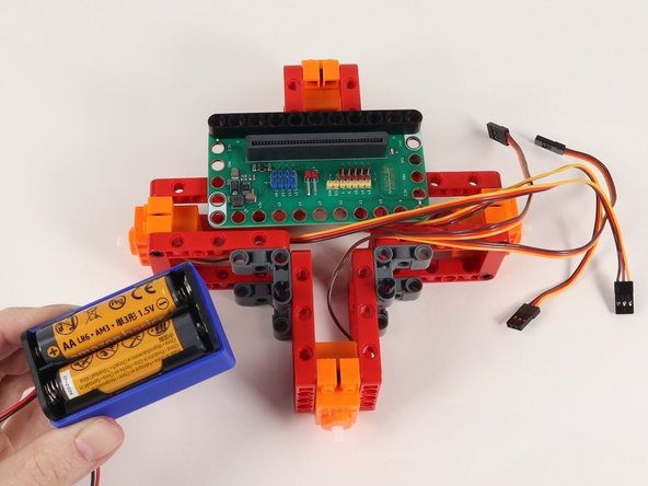
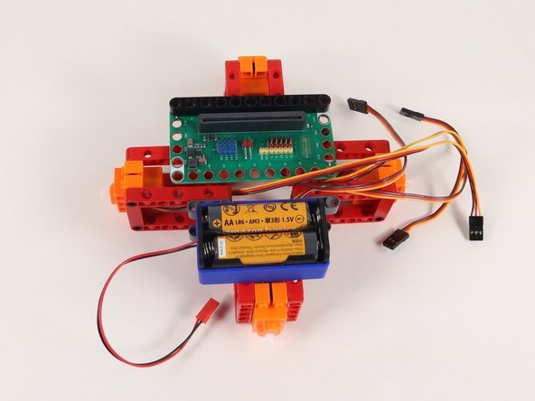
Turn the Rover around so it is facing away from you, as if you were driving it from inside or behind it.
-
Add 2 black pins to the 90° connectors and attach the battery pack to these pins.
-
-
-
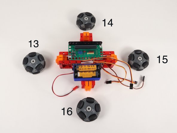
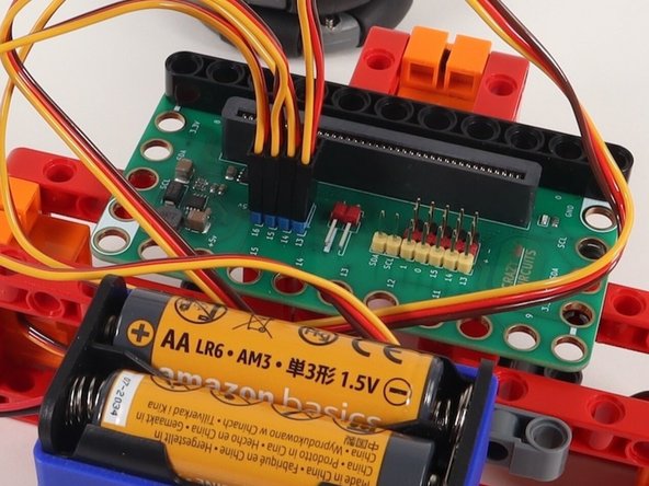
The numbers shown in the photo correspond to the pin each servo will connect to on the Bit Board.
-
Plug the left servo connector into the row for Pin 13. The orange wire should go to the pin closest to the 13 on the board, the red wire goes into the +5v row, and the brown wire goes into the - row, which is ground.
-
Plug the front servo into the row for Pin 14, matching the orientation of the servo connector for the left servo.
-
Plug the right servo into the row for Pin 15, matching the orientation of the servo connector for the other servos.
-
Finally, plug the rear servo into the row for Pin 16, matching the orientation of the servo connector for the other servos.
-
-
-
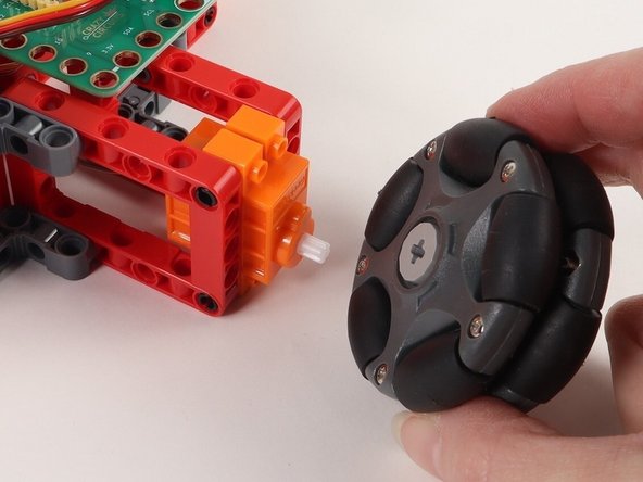
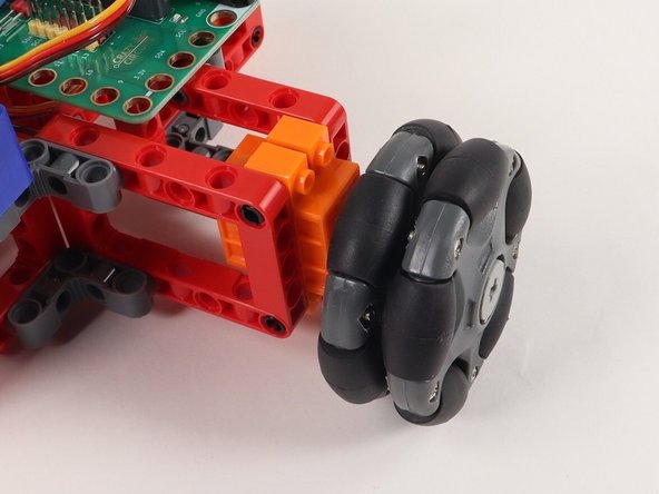
Hopefully you got your wheels sorted in Step 3. If your wheels are ready to go you can add them now.
-
-
-
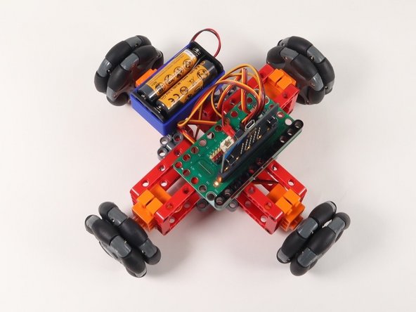
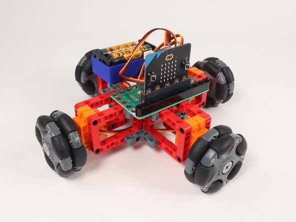
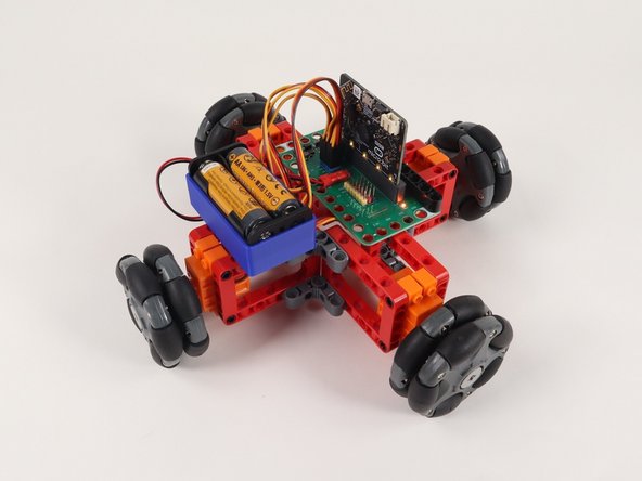
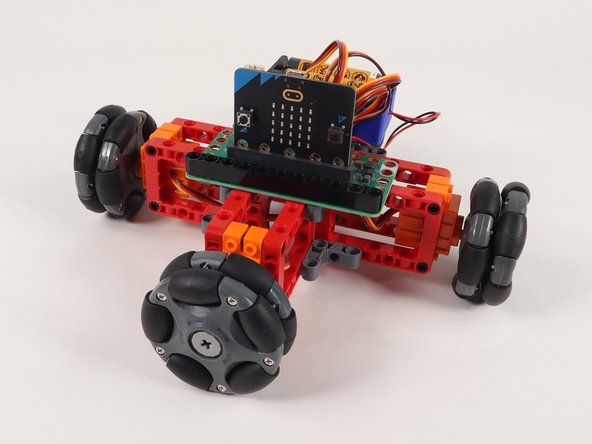
Check it out! You've assembled the Omni Wheel Rover (4 Wheels).
-
Next we'll load some code and get it running.
-
-
-
If you've never used a micro:bit before you'll want to check out this guide: Bit Board V2 Setup and Use
-
We're going to load the following code for our Omni Wheel Rover (4 Wheels) Test program: https://makecode.microbit.org/_MD5Fik4aL...
-
This test code is very simple. Be aware that your rover will start moving two seconds after the code is loaded so be ready for that!
-
If you want to change that just edit the pause block in the on start section. (Note: 2000 milliseconds equals 2 seconds.)
-
Another trick is to just pop the wheels off when you upload the code. :)
-
-
-
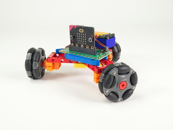
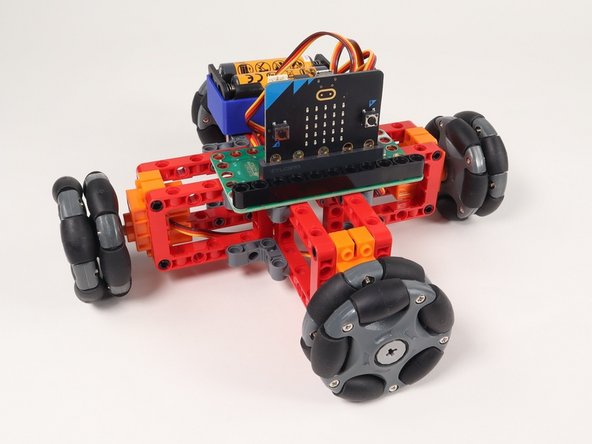
Once you've got the code loaded, the micro:bit inserted into the Bit Board, and the battery pack plugged in, let your 4 wheeled Omni Wheel Rover go!
-
-
-
Check out a variation of this project with 3 wheels instead: Omni Wheel Rover (3 Wheels)
-