Introduction
This Omni Wheel Rover is an alternative Rover you can build by adding Omni Wheels and a third servo to our standard Rover Kit.
Depending on the Omni Wheels you purchase we may also recommend 3D printing new hubs. (See the guide: 3D Printed Parts: Omni Wheel Hub)
Video Overview
-
-
This is an Advanced Build! Besides the parts in the Rover Kit you will need one additional Continuous Rotation 360 Degree Servo and a set of three Omni Wheels.
-
What are Omni Wheels? Check out one of our previous projects, the Omni Wheel Robot, for a good primer on how Omni Wheels work.
-
Just three Omni Wheels? Yes. While an Omni Wheel drive system can work with 4 wheels it can also work with just 3 wheels!
-
Once you see the Omni Wheel Rover moving it should make sense. To move in a specific direction two wheels rotate along their axes and the third does not (or runs at a lower speed).
-
The Rover Kit comes with just two servos, but if you borrow a servo from another kit, or get a third servo separately, you can build this project.
-
You will also need three Omni Wheels. We’ll detail that in Step 3.
-
-
-
Gather the parts needed to assemble the Omni Wheel Rover.
-
You'll find most of the parts in the standard Bit Board Rover Kit but you'll need to have a third servo and the Omni Wheels to complete this build.
-
-
-
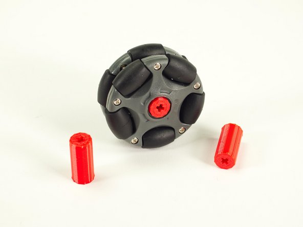
You have a few options for the Omni Wheels.
-
For our previous Omni Wheel Robot We’ve used these Vex Omni Wheels along with a 3D printed adapter we created.
-
Alternately, you can use these LEGO compatible wheels, but the LEGO hub that comes with it doesn’t really work when attached to servos. (It works well for LEGO axles going all the way through and held in place, but not when put directly onto a short servo axle.)
-
We have another 3D printed hub that works well in place of the hub that is included.
-
Check out the guide and grab the files to print your own: Omni Wheel Hub
-
-
-
Our frame will be triangular, which isn’t the easiest thing to build with beams.
-
Most beam building relies on 90 degree angles, but with a few neat tricks we’ll get our triangle.
-
-
-
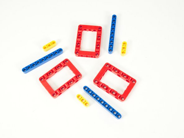
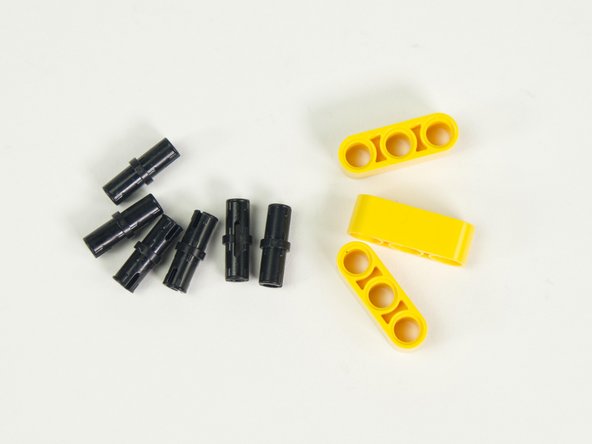
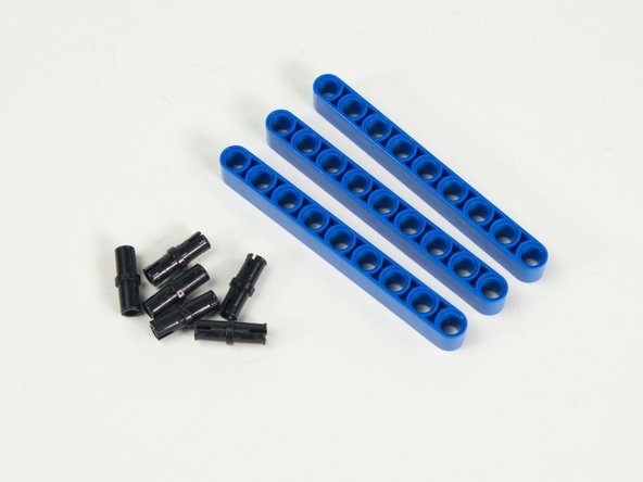
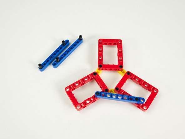
We'll start with 3 red frames, 3 blue 9 hole beams, 3 yellow 3 hole beams, and 12 black pins. (Not shown)
-
-
-
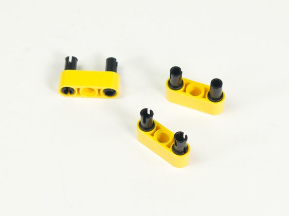
Add two black pins to each yellow beam, on the ends, leaving the middle holes empty.
-
-
-
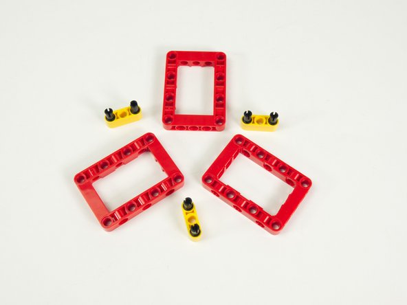
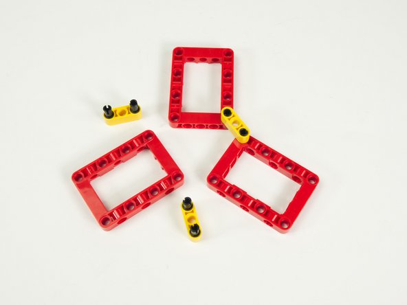
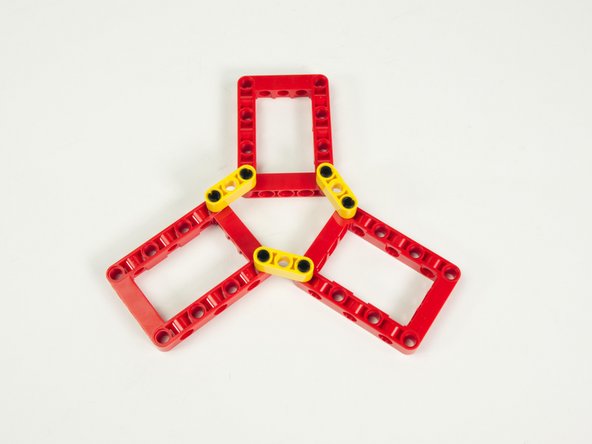
Position the red frames as shown.
-
Add the yellow beams to the frames.
-
The frame can wiggle around, and that’s okay. We’ll secure it in the next steps.
-
-
-
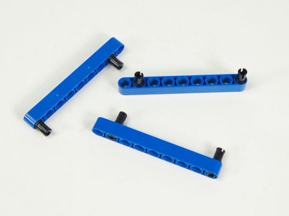
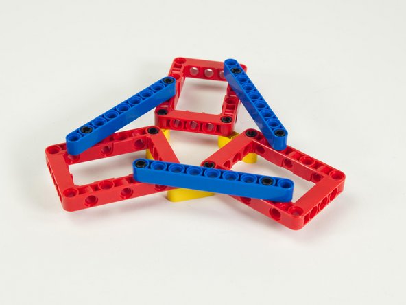
Add two black pins to each blue beam.
-
One pin goes at one end, and the other goes in the second hole on the opposite end.
-
-
-
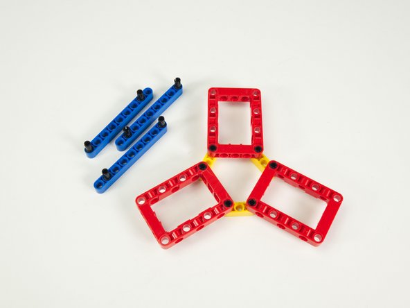
Place a blue beam across two red frames as shown.
-
The pin at the end of the blue beam goes into the hole in the red frame next to the pin on the yellow beam located towards the center of the frame...
-
...and the pin in the opposite side of the blue beam goes into the second hole in the red frame closest to the outside of the frame.
-
Repeat with the other two blue beams.
-
-
-
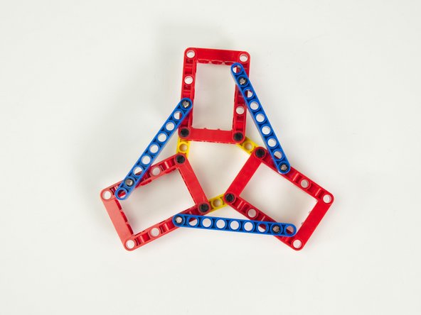
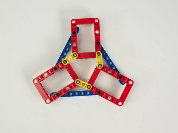
Our triangle frame is now complete. Make sure it looks like the photos.
-
Now, it doesn't exactly look like a perfect equilateral triangle, but it will work fine for our purposes.
-
-
-
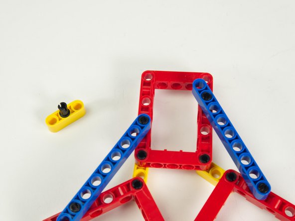
Place a black pin into the middle of a yellow 3 hole beam.
-
Insert this pin and beam combo into the hole in a red frame as shown.
-
The yellow beam can spin freely, but we’ll adjust it to line up with the pins on the Battery Pack when we add that.
-
Note this will be the “rear” of the rover, where the Battery Pack sits.
-
-
-
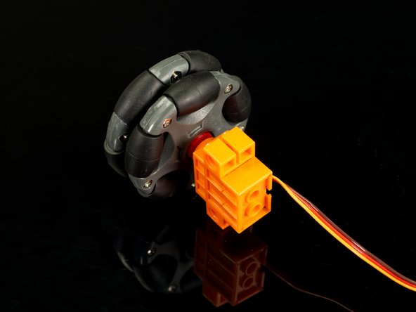
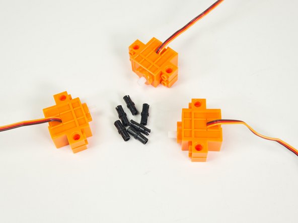
Gather all three servos and 6 black pins.
-
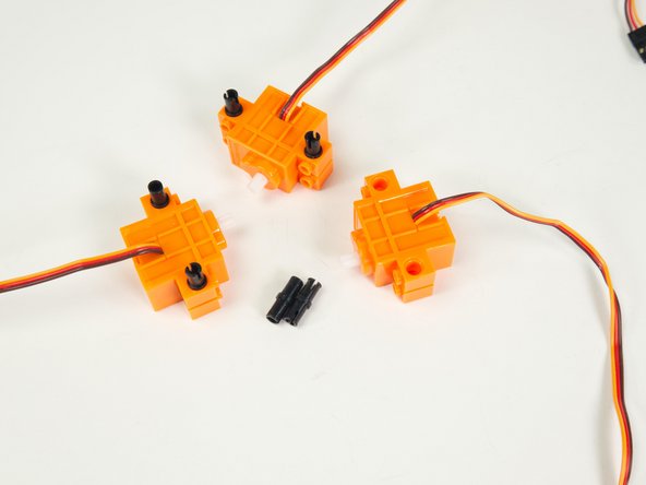
With the wires of the servos facing up, add the black pins as shown.
-
-
-
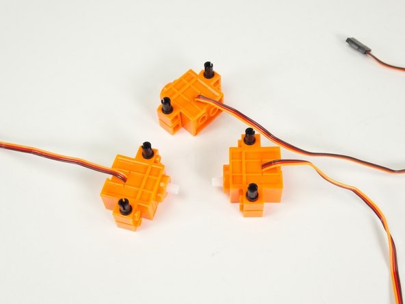
Add a servo to each red frame as shown.
-
Make sure the wires coming out of the servo are facing up so the orientation of the servos are all the same.
-
-
-
Turn the Rover around so the front is facing you.
-
Remember, the 3 hole yellow beam is on the “back” of the Rover.
-
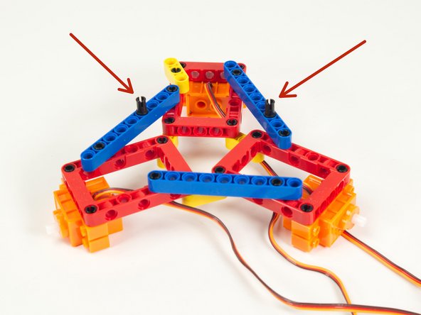
On the lefthand side place a black pin into the fourth hole of the blue beam.
-
On the righthand side place a black pin into the third hole of the other blue beam.
-
-
-
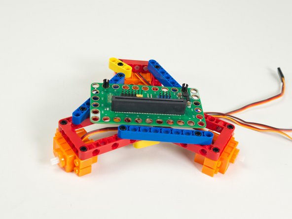
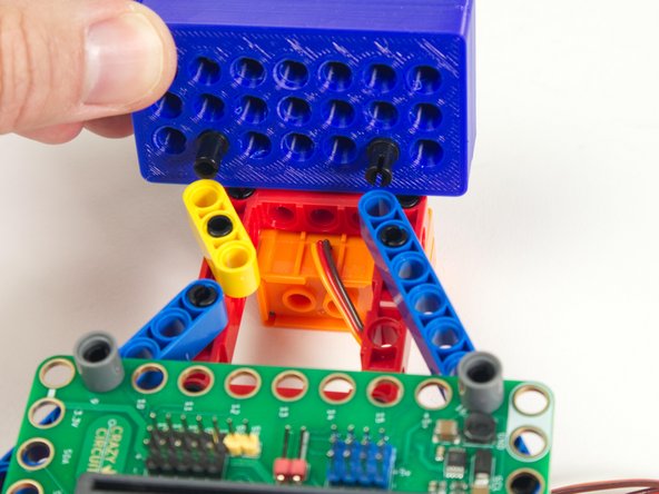
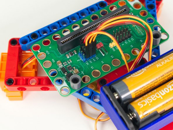
Place the Bit Board onto the pins so the second hole on each side has a pin going through it.
-
Make sure you have the Bit Board facing forward/towards you!
-
Add two gray “one hole” beams onto the pins to hold the Bit Board down.
-
Note that all of the angles will look a little bit “off” but that’s okay.
-
-
-
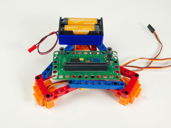
Add two black pins to the Battery Pack as shown.
-
One pin will go into the last hole of the blue beam on the righthand side.
-
The other pin will go into the end of the yellow 3 hole beam.
-
Note you may need to rotate the yellow beam into position so it lines up properly.
-
-
-
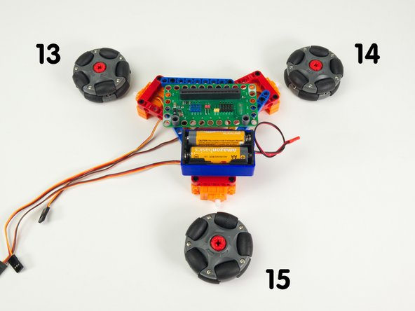
Turn the Rover around so it is facing away from you, as if you were driving it from inside or behind it. Note that we have a left wheel, right wheel, and a rear wheel.
-
This is a little different than the Rover and Tank which just have two drive servos on the left and right.
-
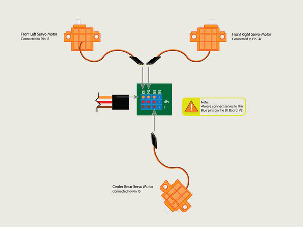
The numbers shown in the photo correspond to the pin each servo will connect to on the Bit Board.
-
-
-
Plug the front left servo connector into the row for Pin 13. The orange wire should go to the pin closest to the 13 on the board, the red wire goes into the +5v row, and the brown wire goes into the - row, which is ground.
-
Plug the front right servo into the row for Pin 14, matching the orientation of the servo connector for the left servo.
-
Finally, plug the center rear servo into the row for Pin 15, matching the orientation of the servo connector for the other two servos.
-
-
-
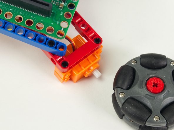
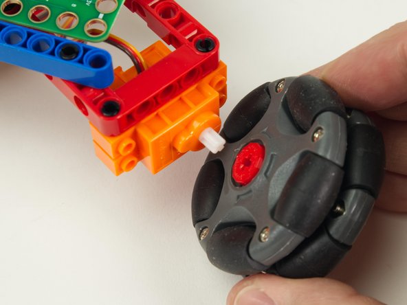
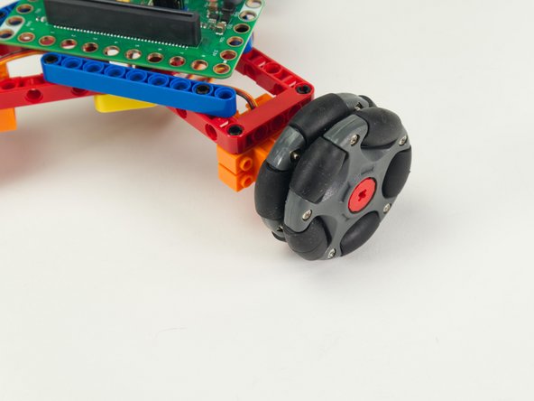
Hopefully you got your wheels sorted in Step 2. If your wheels are ready to go you can add them now.
-
-
-
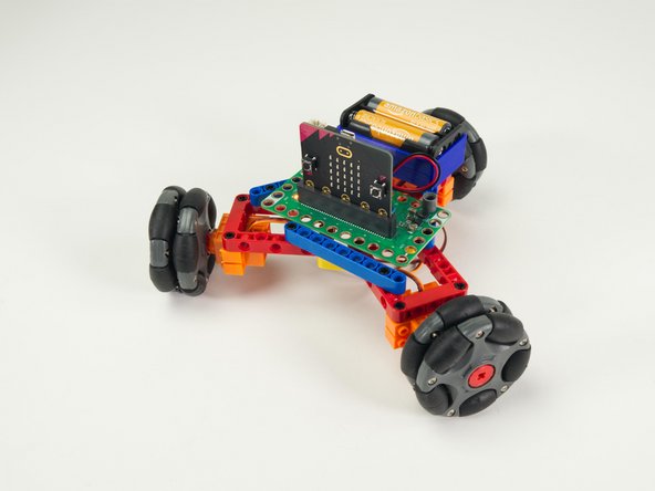
Check it out! You've assembled the Omni Wheel Rover.
-
Next we'll load some code and get it running.
-
-
-
If you've never used a micro:bit before you'll want to check out this guide: Bit Board V2 Setup and Use
-
We're going to load the following code for our Omni Wheel Rover Test program: https://makecode.microbit.org/_g3RYLabyH...
-
This test code is very simple. Be aware that your rover will start moving three seconds after the code is loaded so be ready for that!
-
If you want to change that just edit the pause block in the on start section. (Note: 3000 milliseconds equals 3 seconds.)
-
Another trick is to just pop the wheels off when you upload the code. :)
-
-
-
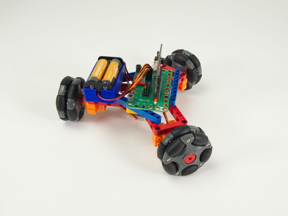
Once you've got the code loaded, the micro:bit inserted into the Bit Board, and the battery pack plugged in, let your Omni Wheel Rover go!
-
-
-
While we cannot add Gripper, Lifter or Sweeper, we can add sensors to the Omni Wheel Rover to expand its capabilities.
-
We’re currently working on a guide to add the Distance Sensor to allow the Omni Wheel Rover the ability to avoid obstacles.
-
In the meantime, you can try changing the code used to test the Omni Wheel Rover and see what you can come up with for unique movements.
-