Introduction
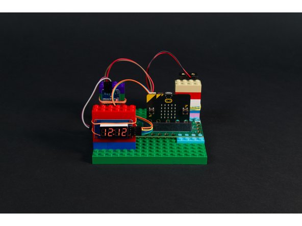
Connect a RTC (Real Time Clock) module to a Bit Board and your micro:bit can function as a clock. We've added a 7 Segment Display so we can see what time it is.
Video Overview
Featured Document
-
-
A "Real Time Clock" (or "RTC") module is a small component that measures the passage of time. Well, that's a clock, right?
-
RTC modules have a few electronic components along with a battery so they'll continue to keep track of the date and time even when not connected to your circuit.
-
We can connect an RTC module to a micro:bit with 4 wires. We need VCC and GND (which will power the module) and then two more wires so the module can "talk" to the micro:bit
-
The two wires use a protocol called I2C to talk to the micro:bit. I2C modules must be connected to pins 19 & 20 on the micro:bit, because those two pins are designated as the SDA and SCL pins for I2C communication.
-
The attached PDF goes into more detail about I2C and is worth a read!
-
-
-
Like most of our Crazy Circuits projects we'll start by putting our Bit Board onto a LEGO baseplate. This lets us easily connect parts of our circuit with Maker Tape.
-
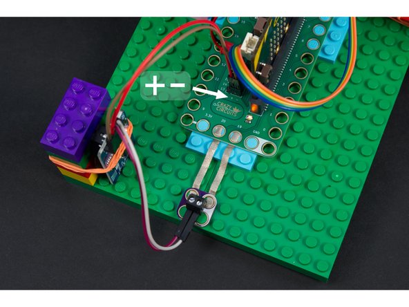
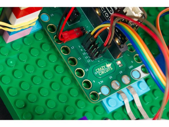
We'll use a Screw Terminal to connect the SCL and SDA up to Pins 19 & 20 of the micro:bit, then plug the VCC and GND for the RTC module directly into the pin headers on the back of the Bit Board.
-
If you have two Screw Terminal Chips you can connect to VCC to 3.3v and GND to GND using Maker Tape.
-
If you don't have any Screw Terminal Chips handy the next step will show an alternative connection method.
-
-
-
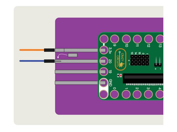
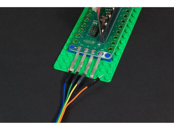
If you don't have any Screw Terminal Chips on-hand, you can connect wires using Maker Tape!
-
We recommend laying down your Maker Tape connection from the Bit Board, and then wrapping it around the edge to the bottom of the LEGO baseplate.
-
Then you can put your Jumper Wires in place and tape them down to create a good electrical connection.
-
You can add more tape if needed, just make sure you do not overlap tape connections between pins!
-
Remember, Maker Tape is conductive on both sides!
-
While this method will work, it's not as mechanically solid as a Screw Terminal Chip, so double-check your connections if your circuit isn't behaving properly. You can always add some non-conductive tape to help hold things in place.
-
-
-
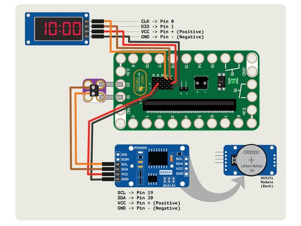
Connect the RTC module to the Bit Board so that the VCC and GND go to + (positive) and - (negative) and then connect SCL to Pin 19 and SDA to Pin 20.
-
Consult the attached PDF for an expanded explanation of the connections.
-
-
-
Connect the 7 Segment Display CLK to Pin 0 and DIO to Pin 1. And just the like the DS3231 module VCC and GND go to + (positive) and - (negative) pin headers so the Bit Board can power the module.
-
-
-
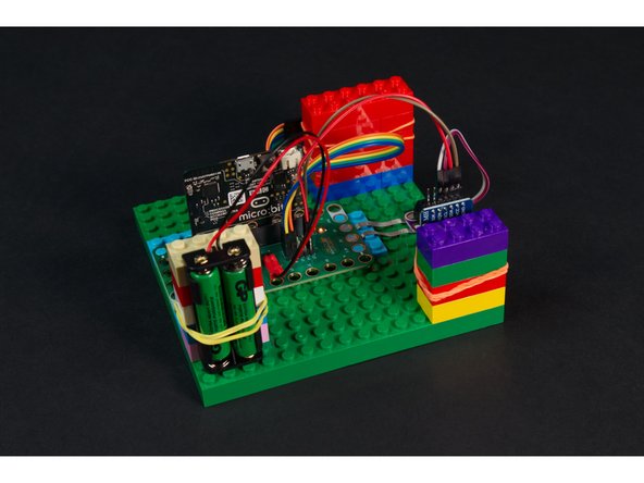
Our Real Time Clock module, and our 7 Segment Display are standard electronic components, and don't have a handy way to connect to LEGO parts.
-
You can build up LEGO pieces in all sorts of interesting ways (and sometimes we do that!) but often the simplest way to mount things is with a few rubber bands.
-
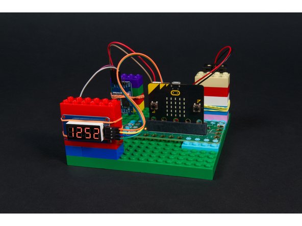
We've got our clock, our display, and our battery pack all held in place with some "LEGO towers" (just a few standard bricks) and with rubber bands. It's simple, and it works. :)
-
Note: We now have a repository of 3D files you can print that work well for holding a 7 Segment Display, Battery Pack, and other parts. See: 3D Printed Parts
-
-
-
Connect a USB cable to the micro:bit and then plug it into your computer.
-
We'll be using makecode.microbit.org to program our board. It uses a simple drag and drop block interface.
-
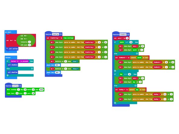
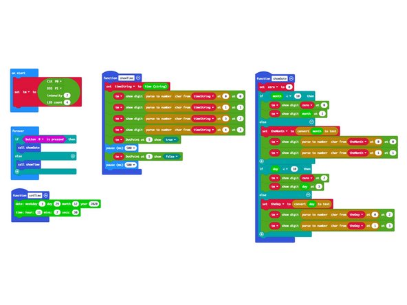
We're going to load the following code for our Real Time Clock 7 Segment program: https://makecode.microbit.org/_7Xc6KPTms...
-
There are a few more steps for this program, so you can load it onto your micro:bit now, but you will need to load it again at least one more time.
-
The attached PDF for this guide goes into great details explaining the code and what each section does.
-
-
-
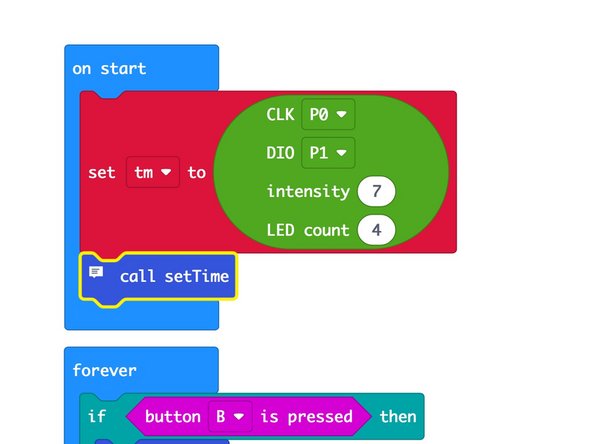
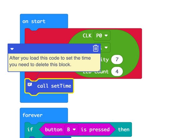
You might notice a block in the on start section labeled call setTime has a small "note" icon. You can click on it!
-
This is a comment, and clicking on it shows you what it says. You can close it with the triangle or delete it with the trash can icon.
-
Comments are used by programmer to make notes for other humans. Computers just ignore the comments, but we humans find them helpful!
-
The comment here lets us know that we need to delete the block after we set the time. We'll explain more in the next step.
-
-
-
Just like a "real" clock, our RTC does not know what time it is (or what day it is) until you tell it. So we'll set the time.
-
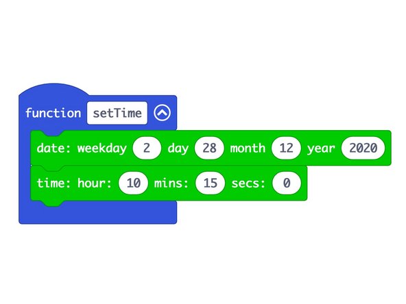
In the setTime function we can set the day, month, year, and the weekday (which is a number representing the day of the week.)
-
We will also need to set the time. Remember that our clock is in 24 hour mode, so 1PM would be 13 for the hour.
-
Once you have the time set you should upload your code. When you do, it will set the time on the RTC module to what we have set in the code. (So don't wait too long to upload the code!)
-
The attached PDF goes into more depth about the specifics of setting the time and explains more about the code.
-
-
-
After you've set the time using the setTime function and uploading your code to the micro:bit you'll need to delete the setTime function from the on start section and upload the code again.
-
If you don't delete the call setTime block after you set the time you'll just reset your clock to the wrong time each time you power on your micro:bit, which defeats the purpose of our RTC module.
-
After the second time you upload your code (after deleting the call setTime block) you should have a functional clock! You can power off the micro:bit, and power it back on, and it should show the correct time.
-
-
-
You can power the Bit Board and micro:bit using a 2 AAA battery pack, or power the micro:bit with a USB cable.
-
Even if you remove the 2 AAA battery pack for an hour, or a day, or a month, when you power up your circuit again it will show the correct time!
-
With a fresh CR2032 coin cell battery in the DS3231 RTC module it should maintain the correct time for about two years. (Don't forget to reset your clock in two years when the battery dies!)
-
-
-
When you power up your amazing new clock it should... show the time. Yup, that's what it does!
-
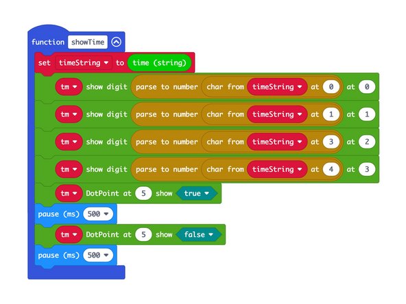
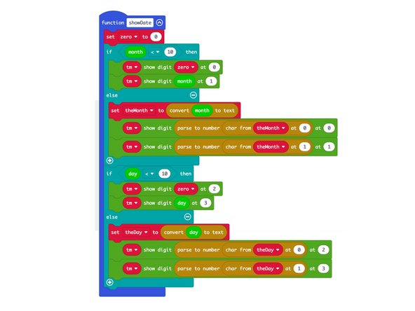
We've added the ability to show the date if you press and hold the B button on the micro:bit. It will only show the month and day, not the year, since we only have space for four digits on the 7 Segment Display.
-
For an in-depth explanation of the code used to display the time and the date check out the attached PDF.
-
-
-
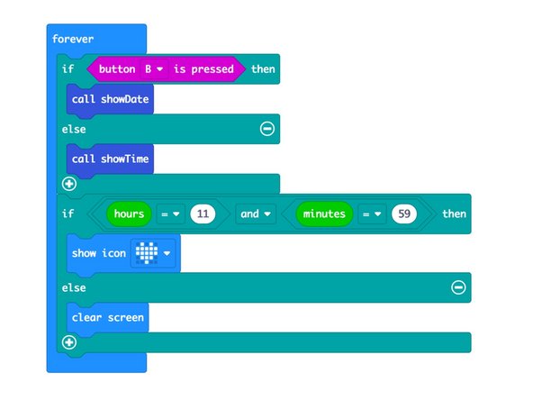
What fun is a clock if it doesn't have an alarm! You can add an alarm in the forever section of the code by checking if it is a specific hour and minute and then doing something.
-
In this code we've added a heart icon that will be displayed on the micro:bit's LED matrix because we love lunchtime and want to be ready eat each day at 11:59AM :)
-
You could just as easily add a sound that would play at a specific time, or move a servo motor, or light up an LED, or anything else you can do with a micro:bit and a Bit Board!
-
Could you turn this 24 hour clock into a 12 hour clock? Adding more code (and a bit of math) should be all it takes.
-


