Video Overview
Build Overview:
Featured Document
-
-
Before continuing, build the Rover using the tutorial found here: Rover Main Body
-
-
-
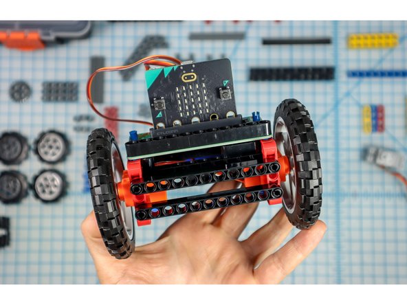
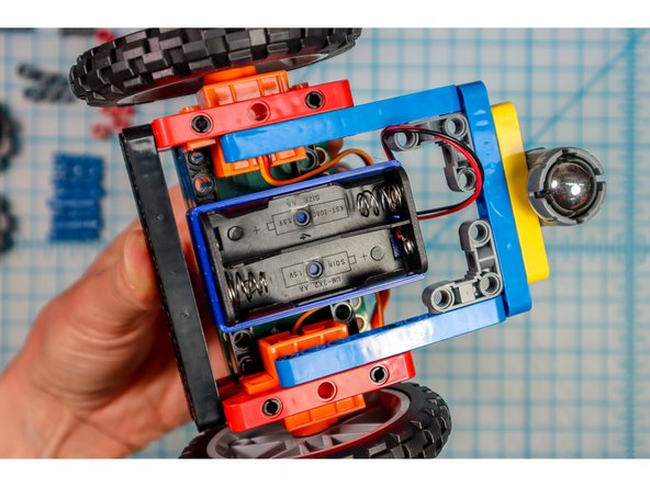
For this project, we'll need to change the location of the battery pack. This will position it on the bottom to make it easy to change the batteries and turn the Rover off.
-
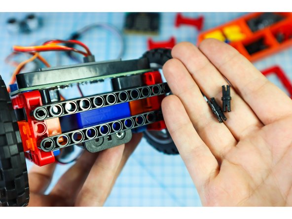
Remove the battery pack from the back of the Rover making sure to also remove the black pegs that held it in place.
-
-
-
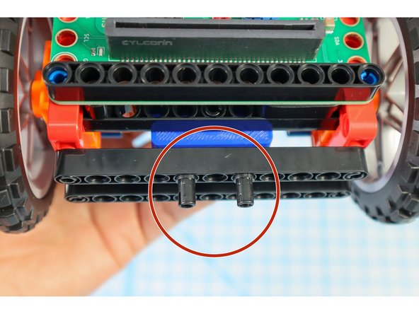
Turn the rover over to view the beams beneath the Bit Board.
-
Place two pins in the center of each black beam as shown.
-
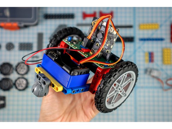
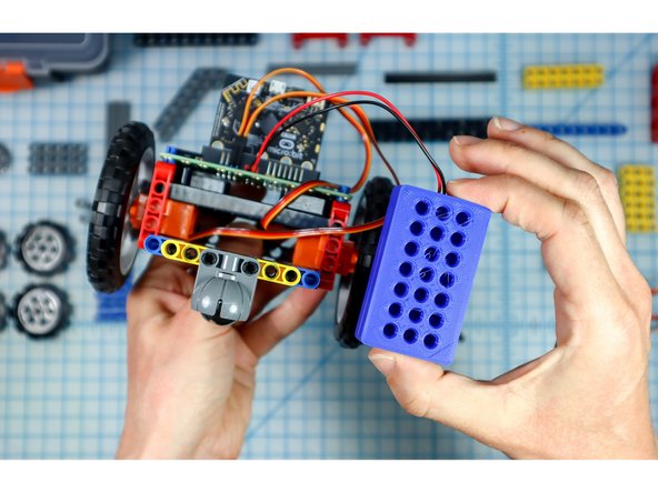
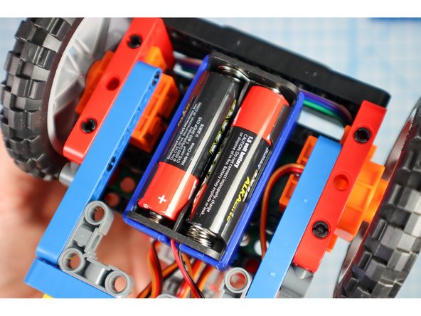
Attach the battery pack to the bottom of the Rover using the pins.
-
Make sure the battery pack is still plugged in before continuing.
-
-
-
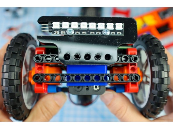
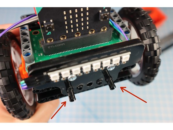
Add two pins to the front of the rover where shown.
-
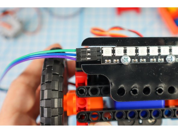
Attach the Neopixel strip assembly to the pins.
-
-
-
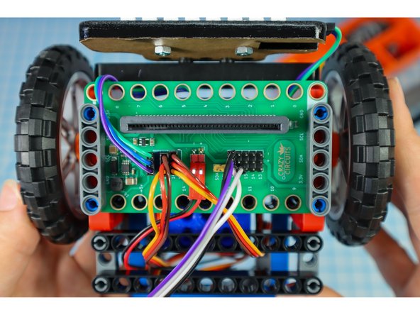
Grab a set of wires and connect three of them to the NeoPixel strip, making note of what color is connected to IN, VCC and GND.
-
Connect the other end of the wires to pin 16 (IN), + 5V (VCC), and - (GND).
-
-
-
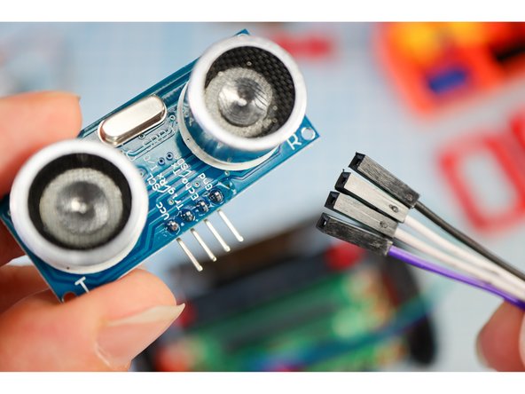
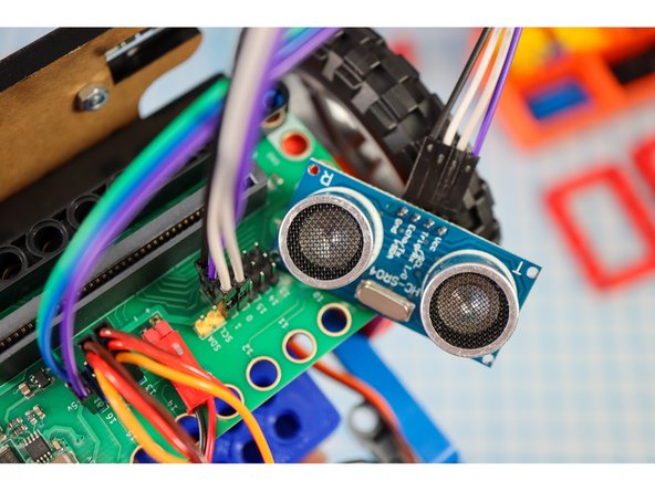
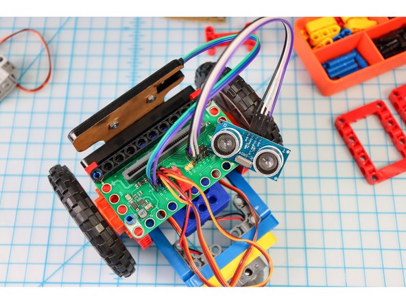
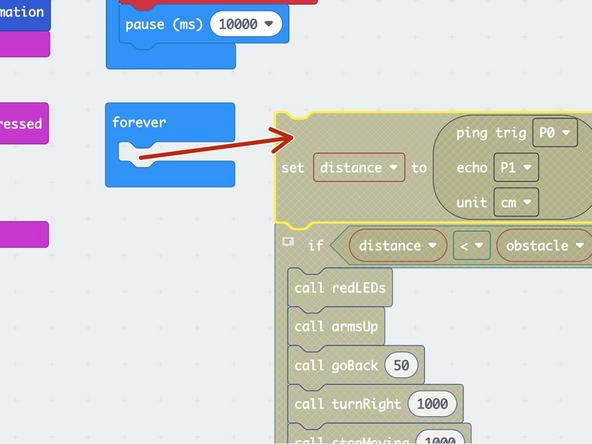
Use 4 wires to connect the Distance Sensor to the Bit Board like this: Trig to Pin 0, Echo to Pin 1, VCC to "+", and GND to "-".
-
-
-
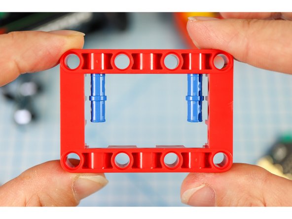
Get a red frame piece, two long pins, and the gray servo motor.
-
From the inside of the frame, insert the blue pins "long-side-in-first" as shown.
-
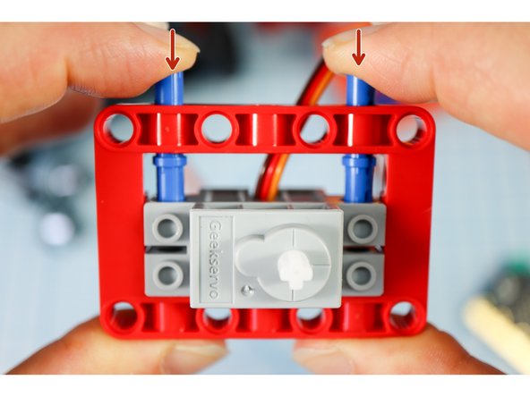
Position the servo motor inside the frame so that the holes align with the blue long pins.
-
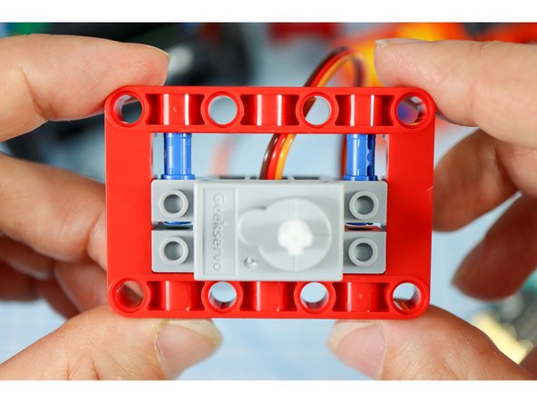
Press the pins down from the outside of the frame causing them to slide into the holes in the motor as shown.
-
Note: The blue pins will only go through the motor halfway. This is a bit of a nontraditional build strategy, but it works for our purposes!
-
-
-
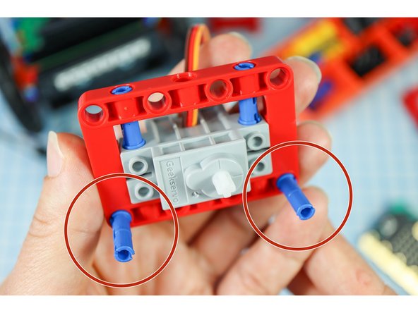
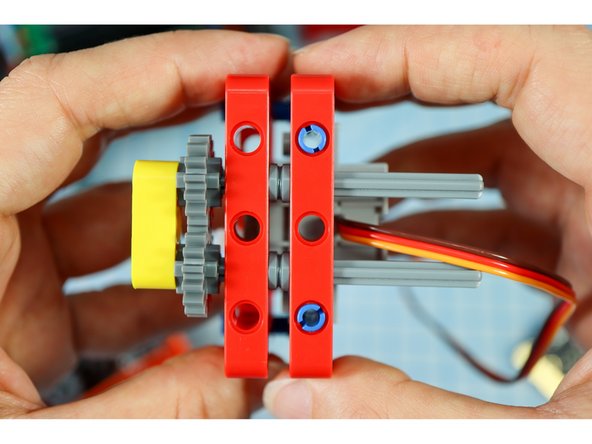
Add two blue pins to the front of the red frame as shown.
-
-
-
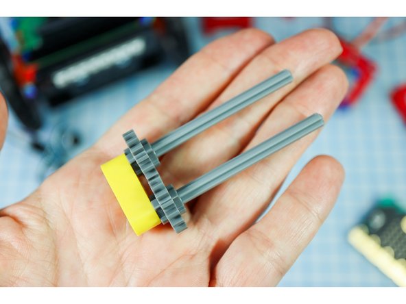
Insert 2 axles with flat ends into the outer holes of the yellow beam, and thread on the gears.
-
Push the pieces down until they stop, interlocking the gears.
-
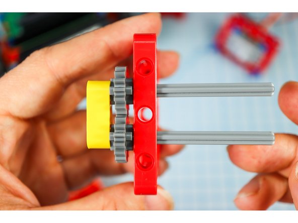
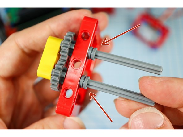
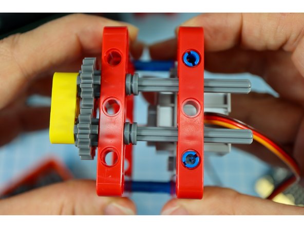
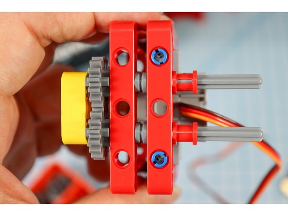
Insert the axles into the second red frame, and secure with two half bushings.
-
-
-
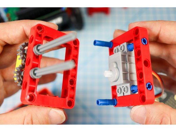
Get the frame piece with the motor attached and connect the two together as shown, with the blue pins on the bottom and the gray axles on the top.
-
-
-
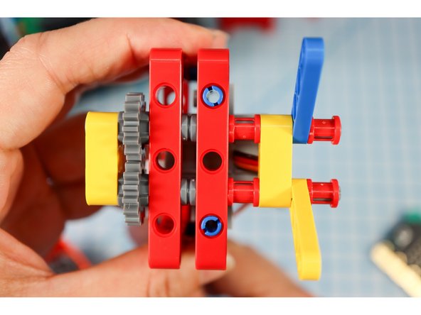
Insert two red full bushings, another yellow beam, two half beams (one on each axle), and two more red full bushings as shown.
-
-
-
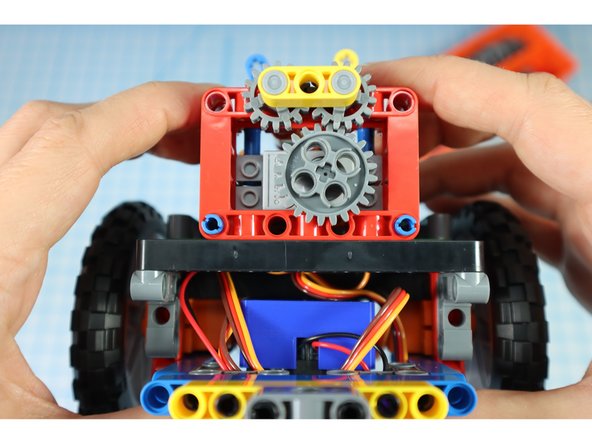
Add the large gear to the motorhead.
-
Align the two half beams so that they meet at the center. You may need to adjust the large gear to do so.
-
-
-
Add two black pins to each of the half beams, with a single gray beam on the top pins as shown. This will be used later to attach the arms.
-
-
-
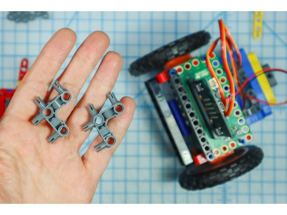
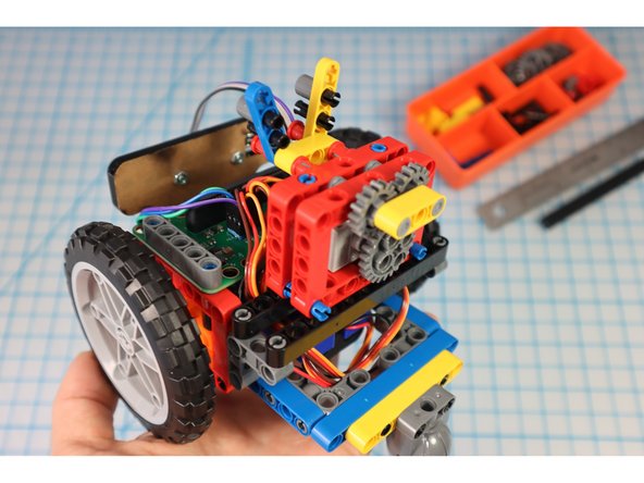
Add two 90-degree connectors to the back of each red frame as shown.
-
-
-
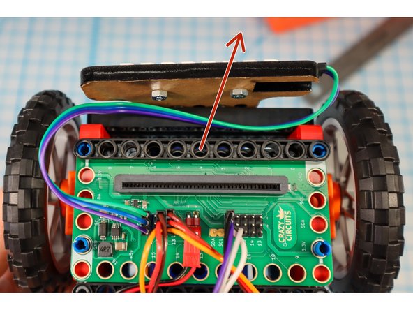
Move the Bit Board forward to give it more room in the rear.
-
Remove the black beam.
-
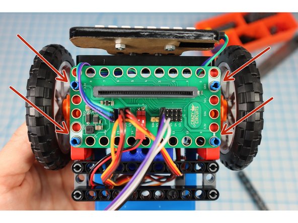
Reposition the Bit Board so that the blue pins go thru the last hole as shown.
-
Secure with two gray beams.
-
-
-
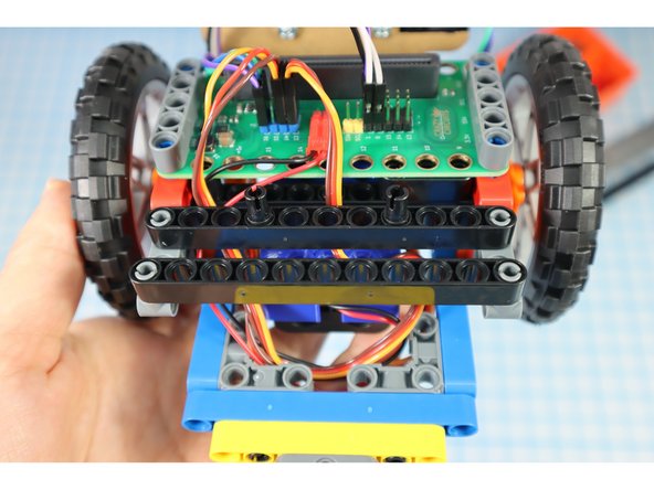
Add two black beams to the rear supports as shown.
-
Add two pins to the beam closest to the micro:bit as shown.
-
-
-
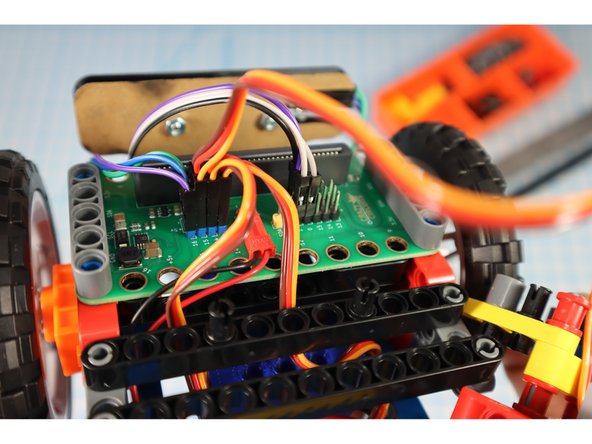
Connect the gray servo motor to pin 15 using the blue (5V) pin headers.
-
-
-
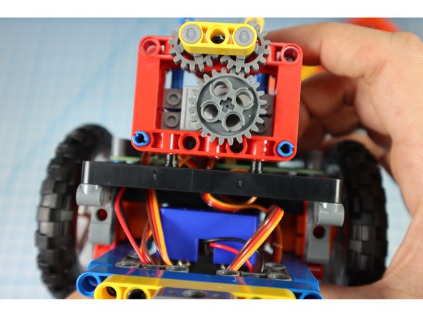
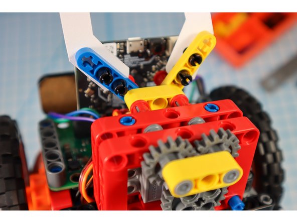
Add the arm gear assembly to the pins as shown.
-
-
-
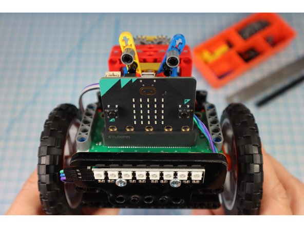
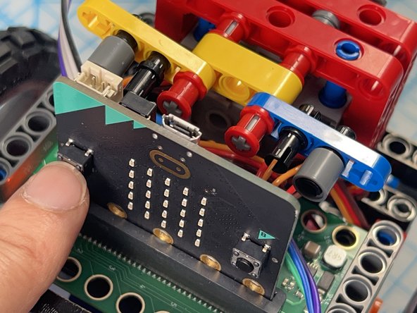
Insert the micro:bit.
-
-
-
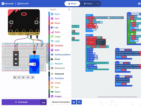
Upload the code to the micro:bit: https://makecode.microbit.org/_4yoFkpPP7...
-
Hint: To make the build easier, drag the blocks out of the forever loop while building to stop the 'bot from "running away!" Or, you could also just pop off the wheels while you work.
-
-
-
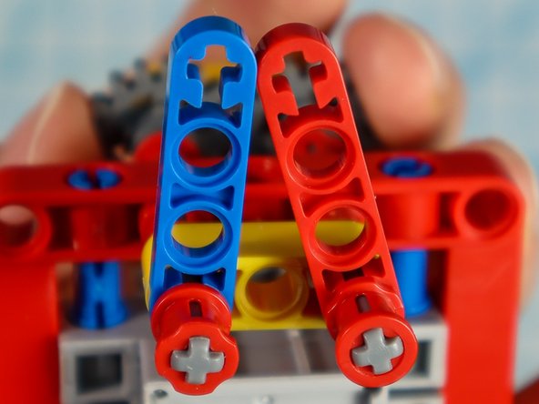
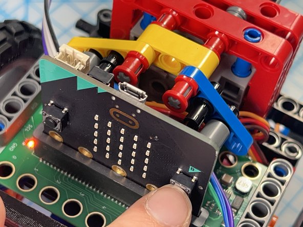
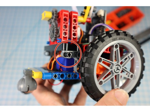
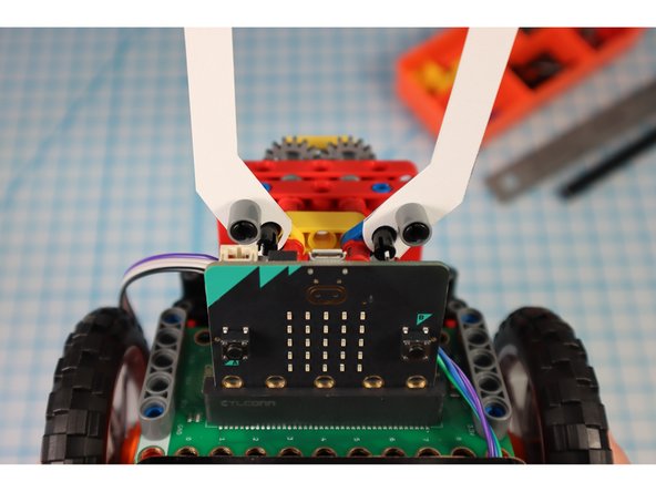
The code is set up so that you can press button "A" to move the arms to the up position and press button "B" to move the arms to the down position. The down position is default.
-
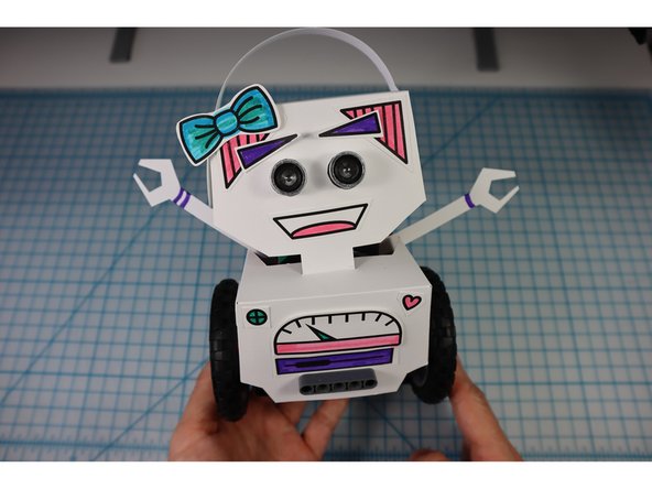
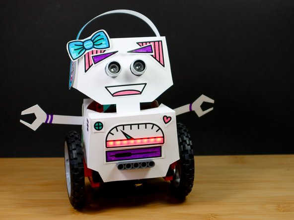
Adjust the Gears so that when you press "A" the starting angle looks like photo 1 and when you press "B" the end angle looks like photo 2.
-
-
-
Add two pins to the front as shown.
-
Add a pin to each of the gray supports on the back as shown.
-
-
-
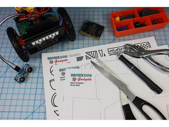
Print out the template on heavy paper or cardstock.
-
You might choose to print the template on colored paper to give your bot some personality!
-
-
-
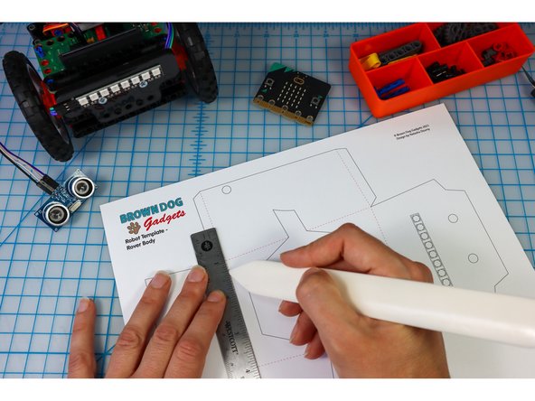
Use a bone folder or pen to score along the dotted lines to make it easier to fold later.
-
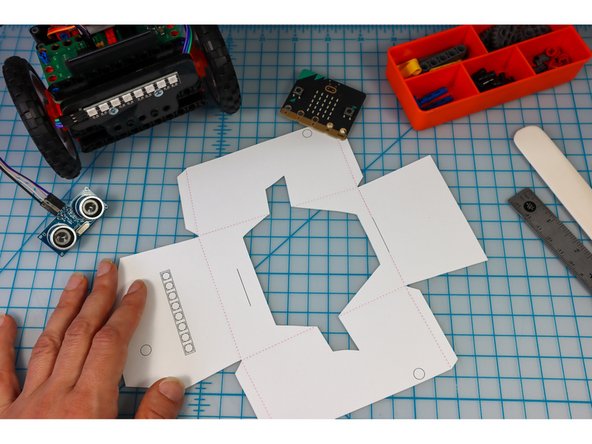
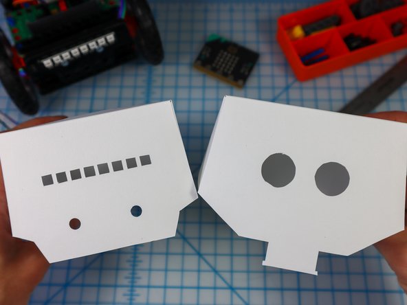
Cut out the head and body template along the solid lines using a craft knife for the interior shapes and scissors or a craft knife for the perimeter.
-
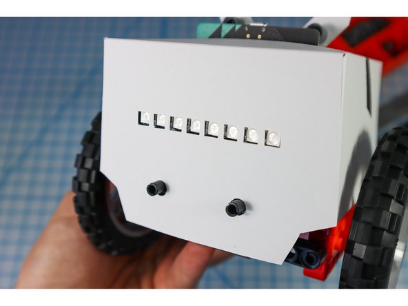
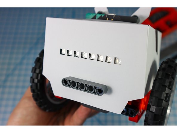
On the body, the location of the NeoPixel strip is shown. You could choose to cut it out or to let the LEDs shine through the paper. I chose to cut mine out to see the location of the LEDs easily.
-
-
-
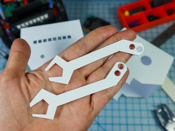
Use a hold punch to punch out the holes in the arms and the 4 holes on the body.
-
-
-
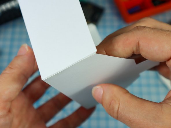
Fold along the dotted lines so that the dotted lines will be on the inside of the project.
-
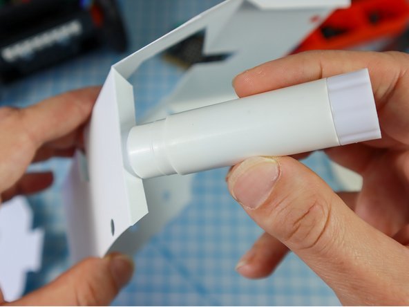
Fold each of the flaps down and apply glue to the outside.
-
Glue the flaps on the inside of each corner as shown to create both the head and the body.
-
-
-
Unpin the pins from the half beams and use them to attach the arms as shown.
-
-
-
Place the paper body over the bot (hint: Move the arms to the up position, and angle it from the back to get the hole around the electronics,.)
-
Use a beam to secure the front in place as shown.
-
-
-
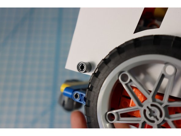
Use pins to connect the body through the holes in the template as shown.
-
Turn on the bot and test that the arms are moving up and down as expected. Adjust the gears as needed.
-
-
-
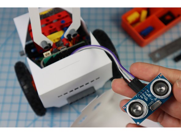
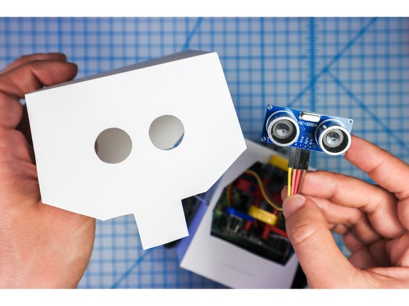
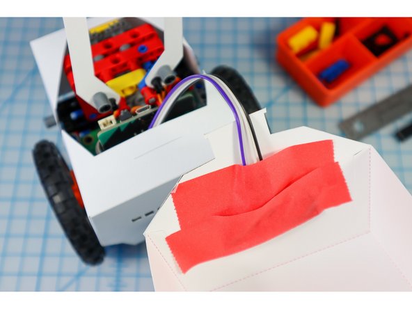
Place the Distance Sensor into the eye circles as shown.
-
Use a few pieces of tape to hold it in place.
-
-
-
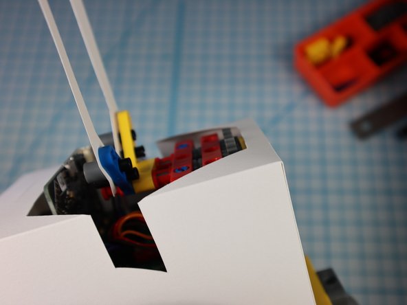
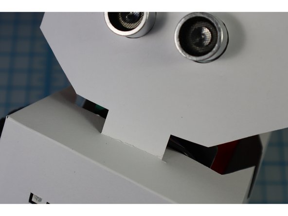
Insert the front head tab through the slit in the front of the body.
-
Insert the back head tab through the slit in the back fo the body.
-
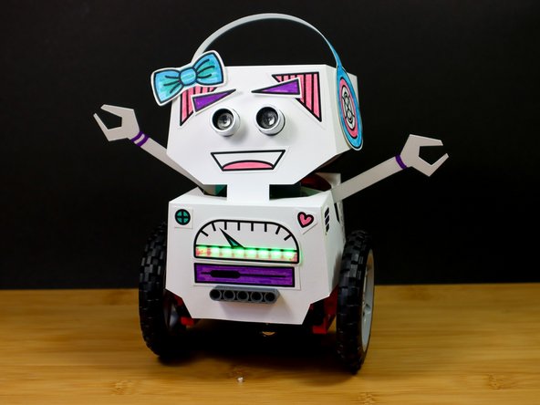
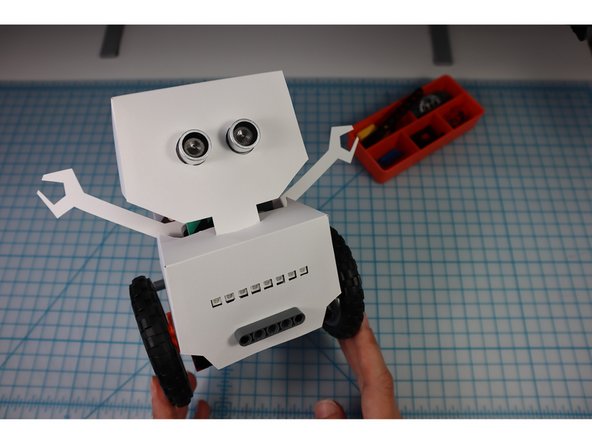
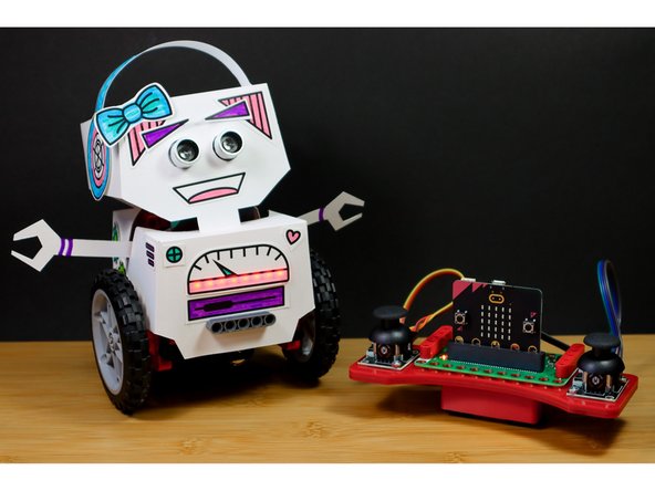
What a cute little robot!
-
-
-
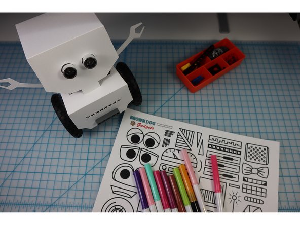
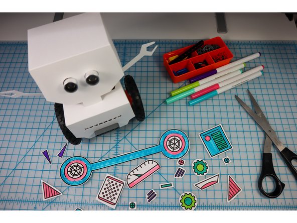
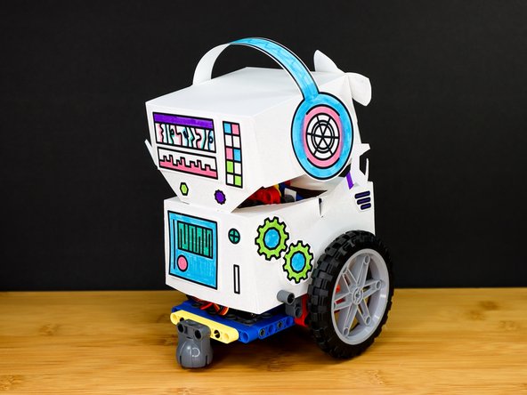
Choose decorations from the template to add to your bot. (Or, create your own!)
-
Color them with markers and glue them to your 'bot!
-
-
-
If you haven't already, add batteries to the battery pack on the bottom.
-
If you haven't already, drag the code blocks back to the forever loop and re-download the code.
-
Now, take your 'bot for a spin!
-
Share your finished bot with the world by tagging us #BrownDogGadgets
-
-
-
When you are done playing with your bot, we recommend turning it off by removing the batteries rather than disassembling it.
-
Tip: It's easiest to remove the battery holder from the bot before removing the batteries, so you don't accidentally crush your bot!
-
-
-
To make a remote control for your bot, continue with this tutorial: Robot - Remote Control - Rover Body
-


Attached Documents
