Introduction
Let's build a Rover! This project uses a set of LEGO Technic components along with our Bit Board, a micro:bit, and two servos to build and program a rolling Rover.
Once you have your Rover built other guides will show you how to extend the programming and add accessories and capabilities to the Rover.
Video Overview
-
-
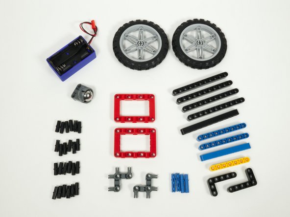
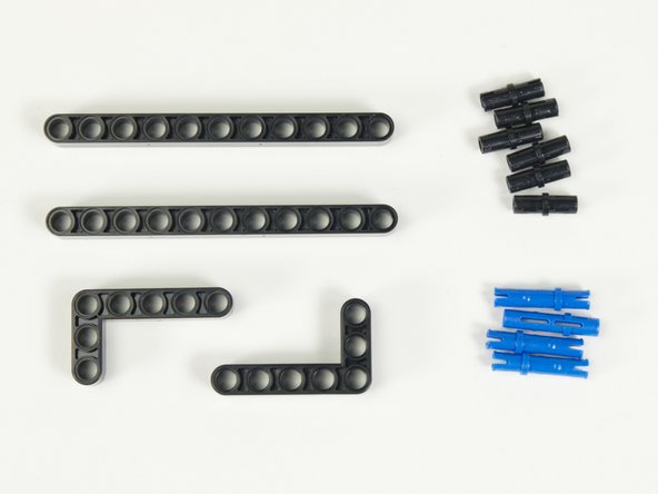
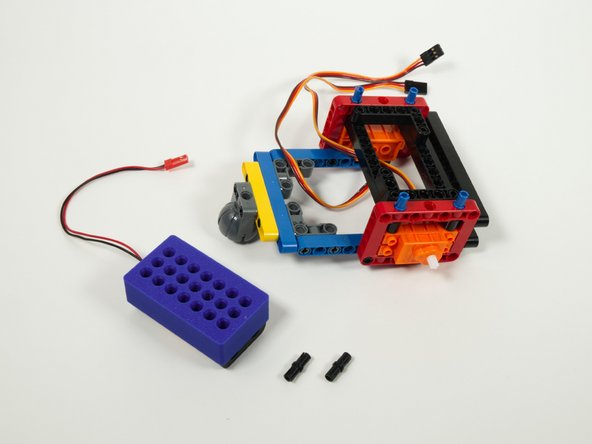
Gather the parts needed to assemble the rover.
-
Besides the beams, pins, frames, and other pieces there are two large wheels, and a blue battery pack.
-
The blue battery pack is a Technic-compatible 3D printed part that we'll use to hold the rover's battery pack.
-
Note: You will need to put the black rubber wheels onto the light gray rims.
-
-
-
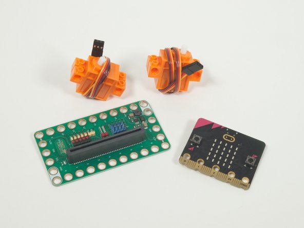
You'll also need a Bit Board and micro:bit, along with two (orange) Brick Compatible Continuous Rotation 360 Degree Servos.
-
-
-
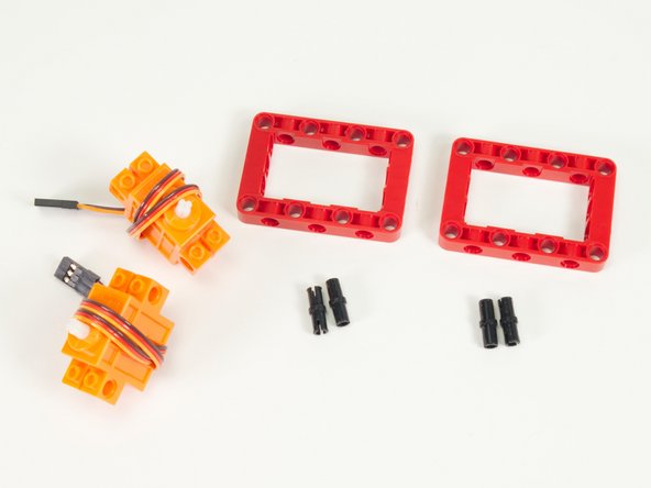
We'll start by attaching the servos to the red frame pieces using pins.
-
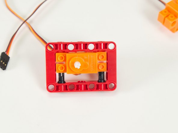
Each assembly will need one servo, one frame, and two black pins.
-
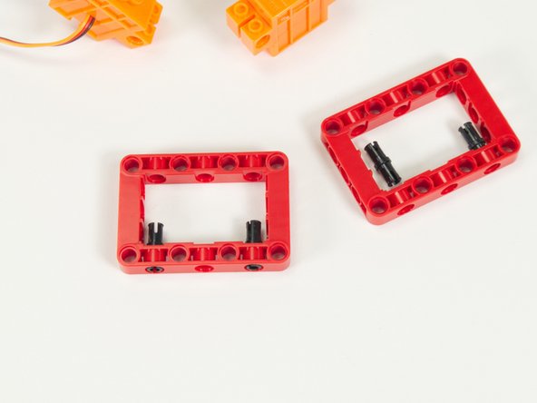
Insert the pins on the inside of the frame as shown.
-
-
-
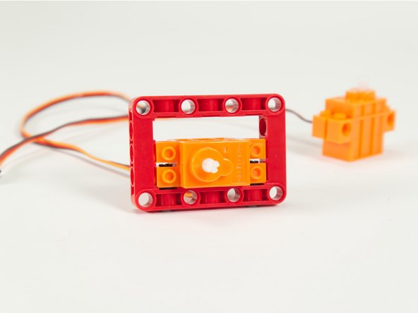
Slide the servo inside the red frame and press it down onto the pins.
-
Note: For the second servo you'll need to flip it over so that it mirrors the orientation of the first one.
-
-
-
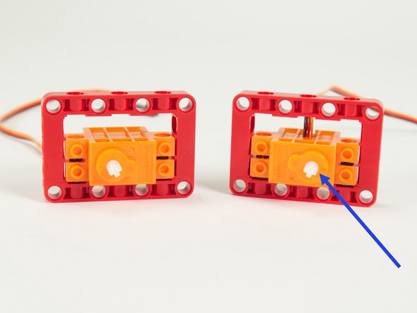
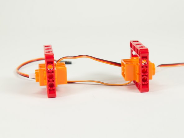
Your servos should look like this.
-
Notice the placement of the shafts on each assembly.
-
The shafts are not centered on the servo, and we consider the side the shaft is closest to the "front" of the servo.
-
-
-
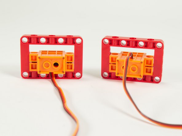
If you turn them around to view from the back you'll notice how one set of wires is on top and one set is on the bottom.
-
If they don't match this configuration make the needed changes before moving on.
-
-
-
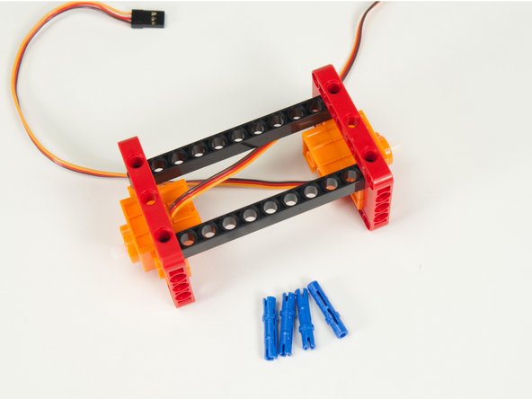
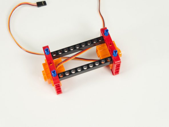
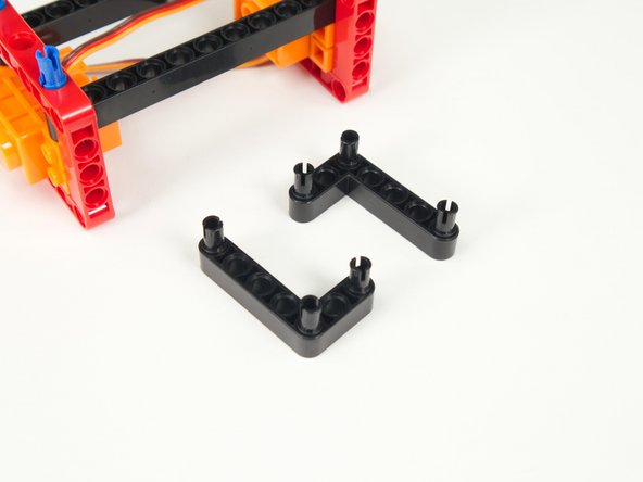
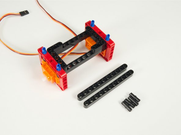
We'll use two long black beams to connect the servos together into a frame, and then two L-shaped black beams to stabilize the frame a bit more.
-
-
-
Slide the long beams in place inside the frame on top of the servos.
-
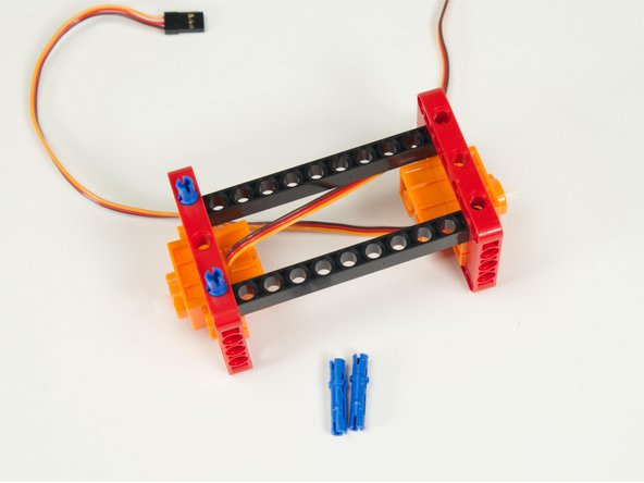
Use the long blue pins to hold the beams into place.
-
Note: The long pins should go in 2/3rds of the way, so make sure you have the orientation correct. (1/3rd should stick out the top.)
-
-
-
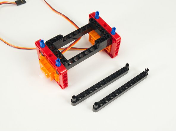
Place pins at the ends and the corner of the two black L-shaped beams as shown.
-
-
-
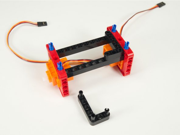
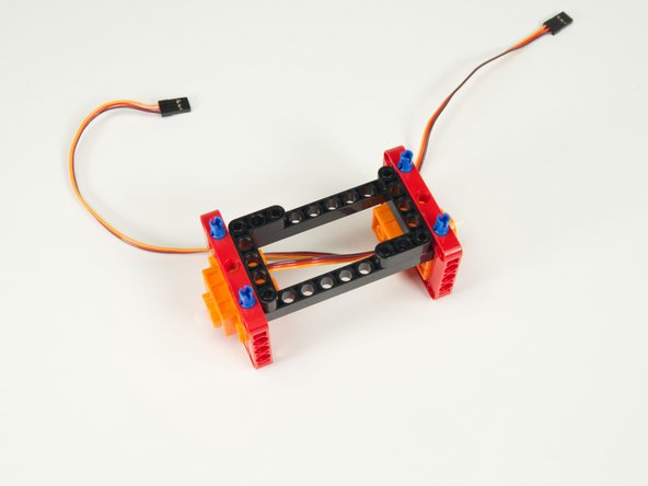
Press the L-shaped beams into place.
-
These will help keep the frame squared up so it doesn't wobble in the X & Y axes.
-
-
-
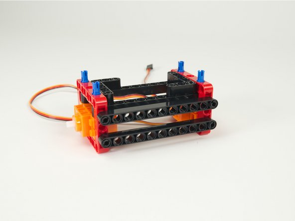
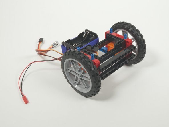
We've got two more long beams to add. These will go on the front.
-
Add two black pins to each black beam and attach them as shown.
-
These beams will be used as connection points later on when we add accessories to our rover.
-
-
-
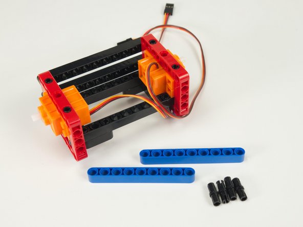
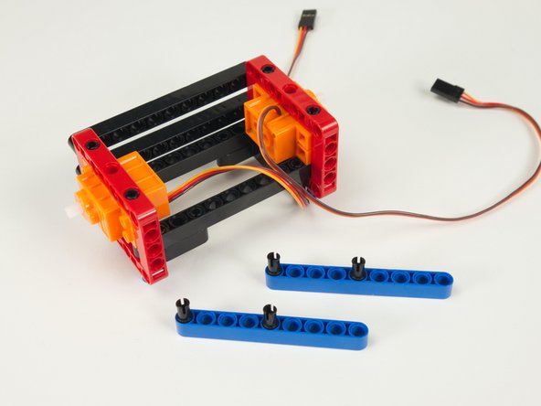
Now that we've got the main frame assembled, and the front beams in place, let's turn the rover around and upside down to work on the back side.
-
Place black pins into the first and fifth holes of the two blue beams.
-
-
-
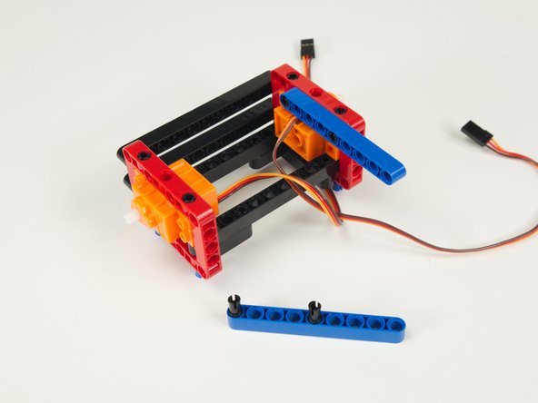
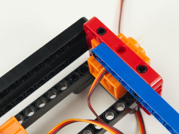
Press one of the blue beams into place on the inside of the frame as shown.
-
Make sure to lay the servo wire flat against the body of the servo and into the groove for the wire before attaching the blue beam.
-
Remember, we're now working on the rover upside down. Don't worry, we'll flip it back to right side up soon.
-
-
-
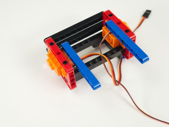
Add the second blue beam, pressing it into place opposite the previously added beam.
-
Once both beams are snapped securely into place we can move on to the next step!
-
-
-
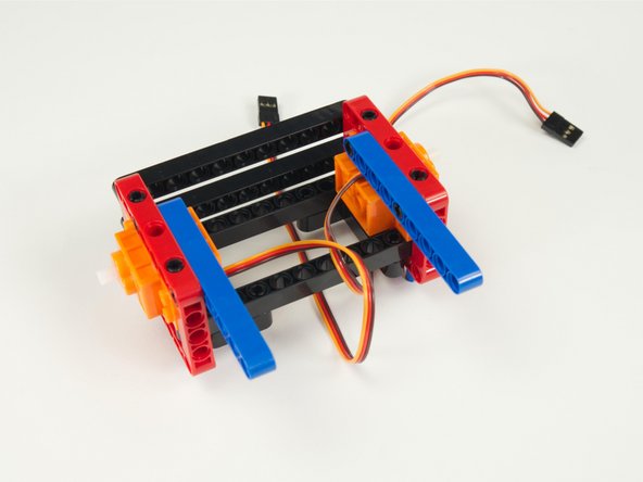
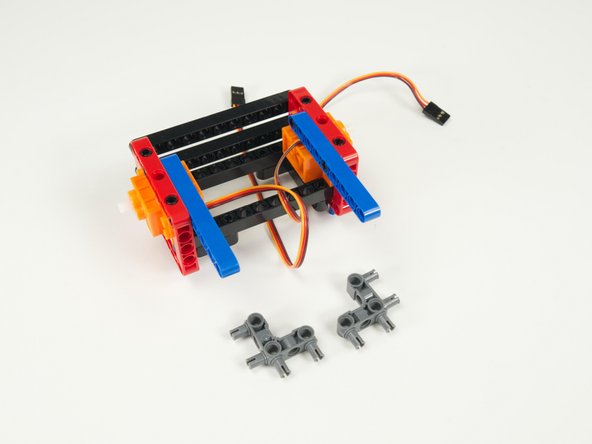
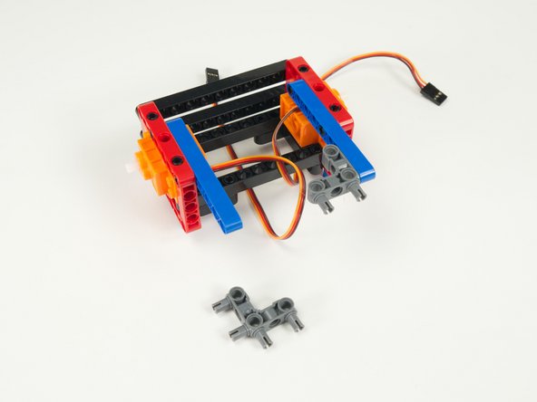
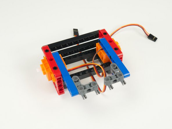
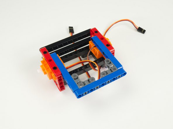
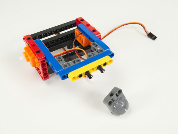
Add the two gray 90 degree connectors to the blue rear stabilizer beams as shown so the pins are facing towards the rear of the rover.
-
-
-
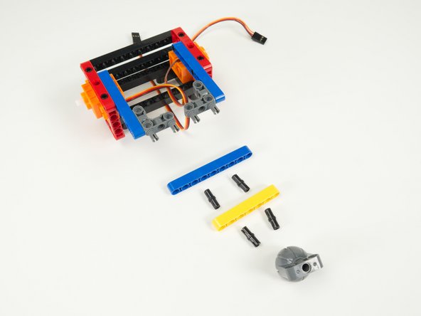
There are two more beams to attach, each using two pins, and then we can add the caster wheel to the back of the rover.
-
-
-
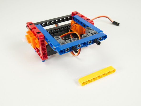
Add the third beam to the gray 90 degree connectors by pressing it into place on the exposed pins.
-
-
-
Place two black pins into the beam we just added, in the third hole from each end.
-
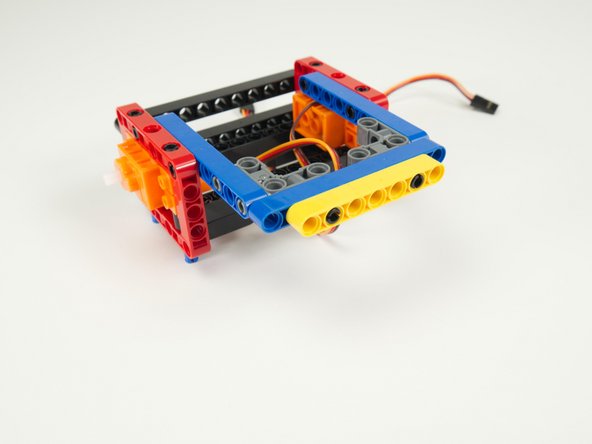
After adding the black pins you can attach the final rear yellow beam.
-
-
-
Add two black pins onto the shorter beam, in the third hole from each end.
-
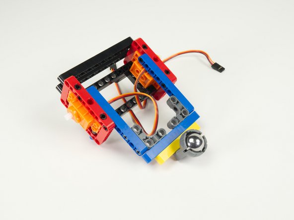
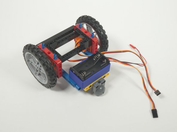
Press the caster wheel into place.
-
Remember to add the caster wheel upside down since our rover is currently upside down.
-
Once the wheel is attached the rover should tip down due to the weight of the steel ball.
-
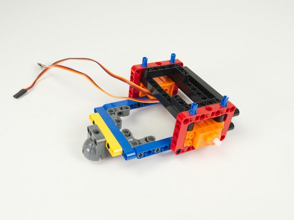
Now is a good time to flip the rover over so it's right side up.
-
-
-
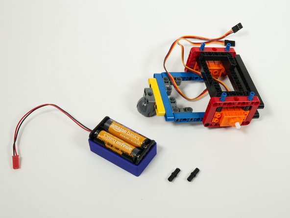
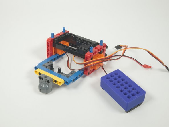
Next up we'll add the blue two AA battery holder.
-
You'll need two black pins to attach the battery holder to the back of the rover.
-
-
-
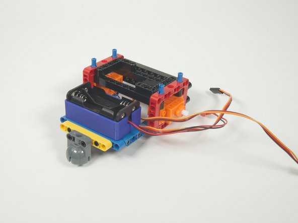
Place two black pins into the gray 90 degree connectors, facing upwards.
-
Add the battery holder by pressing it down onto the pins as shown centering the battery holder on the pins.
-
-
-
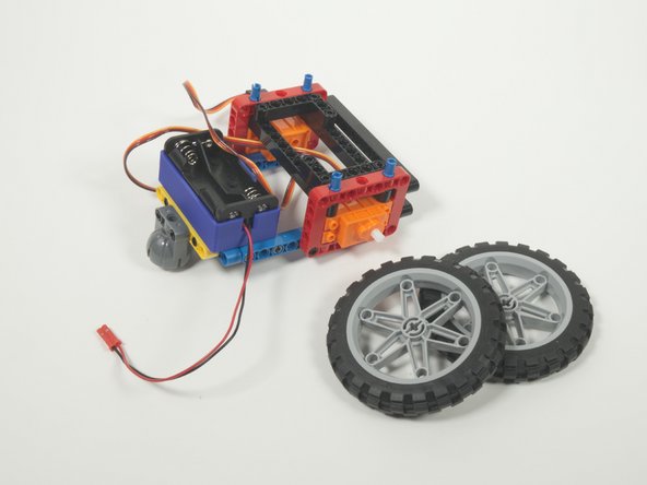
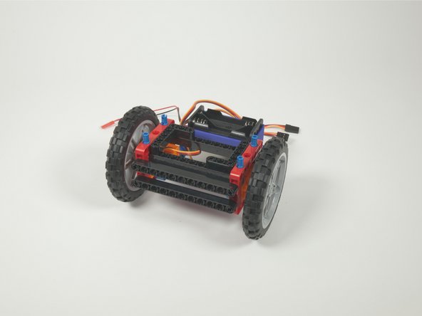
Our rover still doesn't look very rover-ish... because it needs wheels!
-
You can add the wheels now. They just press fit onto the servo shafts.
-
Now it's looking more like a rover!
-
-
-
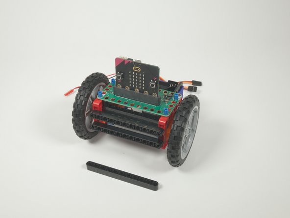
We've already got four blue pins sticking out of the top that we added in Step 8. The Bit Board will fit right onto those pins.
-
Make sure the front of the Bit Board (and front of the micro:bit) are facing forward on the rover.
-
We'll add a long black beam onto the blue pins on the front of the Bit Board. This will help hold it securely in place.
-
Once the Bit Board is in place we can turn it around to the back so we can plug things in.
-
-
-
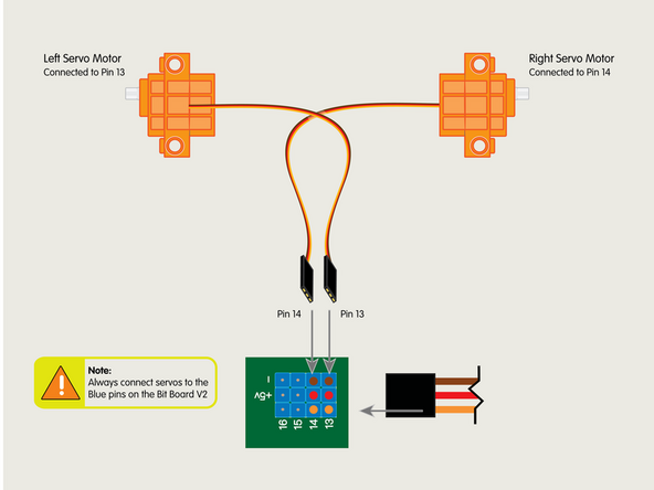
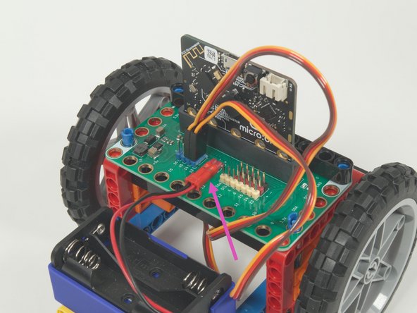
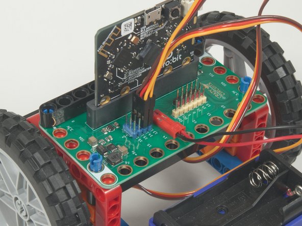
Plug the left servo connector into the row for Pin 13. The orange wire should go to the pin closest to the 13 on the board, the red wire goes into the +5v row, and the brown wire goes into the - row, which is ground.
-
Plug the right servo into the row for Pin 14, matching the orientation of the servo connector for the left servo.
-
Make note of Pin 15. We're not connecting anything to it now, but other guides will use Pin 15 to connect a third servo for additional accessories.
-
-
-
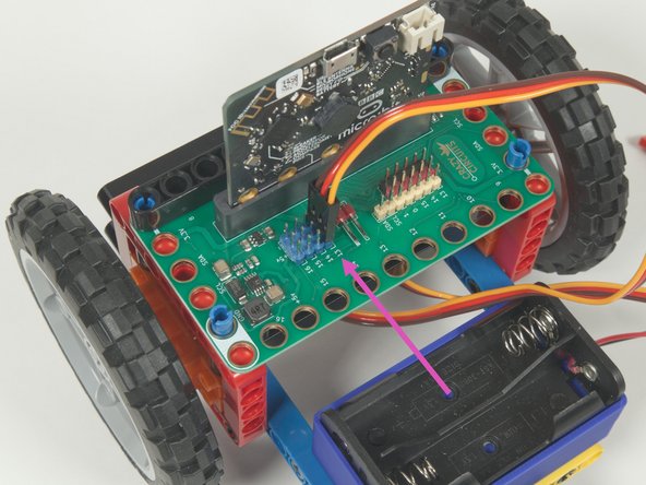
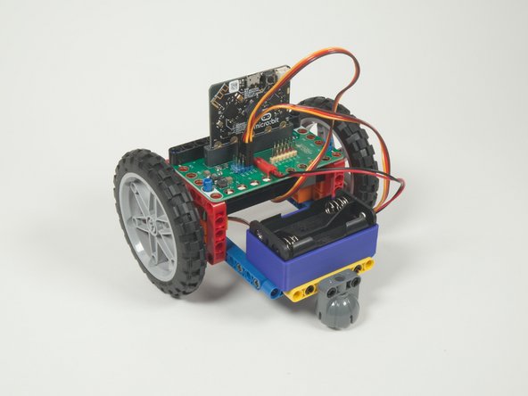
The last connection is the battery pack. It connects to the Bit Board as shown to provide power to the micro:bit and the servos so your rover can move.
-
We've removed the batteries during the build process but will add them back when we're ready to test out rover.
-
-
-
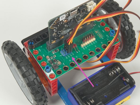
Take a moment to double check your wiring.
-
Are the servo connector oriented the right way? Hint: Make note of where the orange wire is.
-
Is the battery pack plugged in properly? The red wire should align with the + symbol behind the connector pins and you should see two metal pieces showing through slots in the red plastic housing.
-
If everything looks good, keep going!
-
-
-
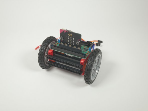
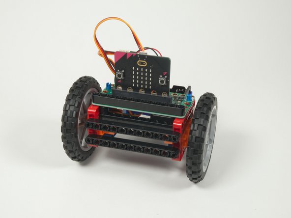
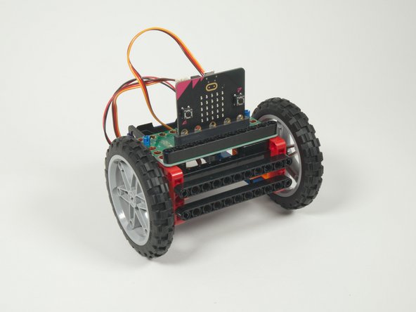
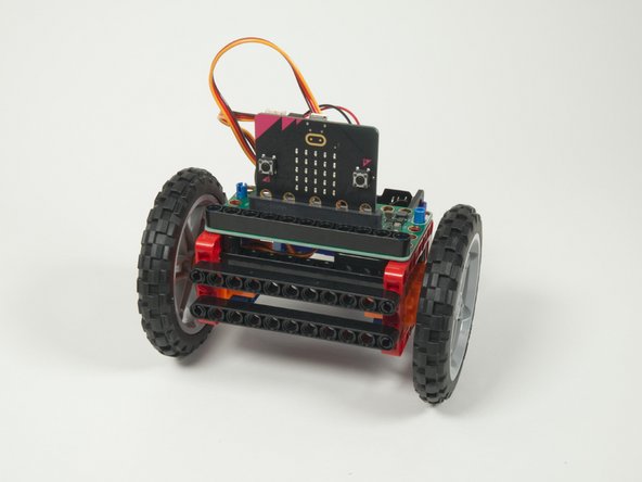
You've just built the Rover! Take a second to admire your work.
-
The great thing about this rover is that it's easy to modify it, to add or remove parts, and experiment.
-
For instance, you could replace the caster wheel with a Pen Holder so the rover can draw while it rolls.
-
We've added another guide for a Rover Gripper you can attach and control, as well as a Lifter and Sweeper.
-
We've got a distance sensor we can add to the front to make the rover avoid running into things.
-
You can add two sensors to make a line following robot.
-
But first... Let's add some code so the rover can move.
-
-
-
If you've never used a micro:bit before you'll want to check out this guide: Bit Board V2 Setup and Use
-
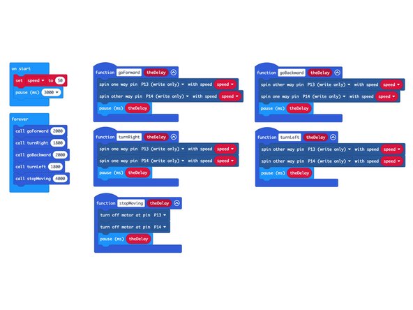
We're going to load the following code for our Rover Test Code program: https://makecode.microbit.org/_euKUdXXKq...
-
This test code is very simple. Be aware that your rover will start moving three seconds after the code is loaded, so be ready for that!
-
If you want to change that just edit the pause block in the on start section. (Note: 3000 milliseconds equals 3 seconds.)
-
Another trick is to just pop the wheels off when you upload the code. :)
-
-
-
Once you've loaded the code and unplugged the micro:bit be sure to add your AA batteries to the battery pack to power your rover.
-
Use a large flat surface. The floor will work well, or a table - just be ready to catch the rover if it gets too close to the edge!
-
Plug the battery pack into the Bit Board, wait three seconds, and your rover should move.
-
If your rover moved properly (forward, turn right, backward, turn left, stop) then all is well and you're ready to extend your Rover by adding accessories, remote control, and other capabilities.
-
We recommend a fresh set of Alkaline batteries (not rechargeable) for maximum performance.
-