Introduction
If you've built our Basic Rover Main Body this is a great accessory. An easy-to-build Gripper than can attach to the front of the Rover.
Video Overview
-
-
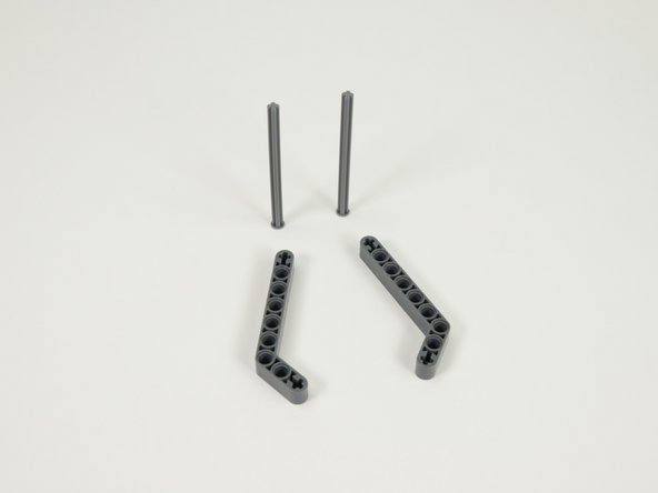
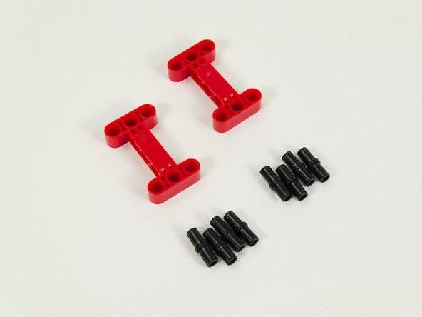
Gather the parts needed to assemble the Gripper.
-
You'll need the following parts along with a Brick Compatible 270 Degree Servo.
-
-
-
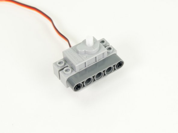
We'll start by adding two black pins to the servo as shown.
-
-
-
Attach a gray 5 beam to the pins on the servo.
-
-
-
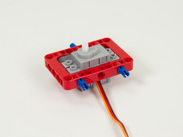
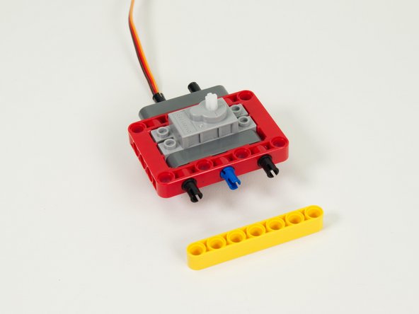
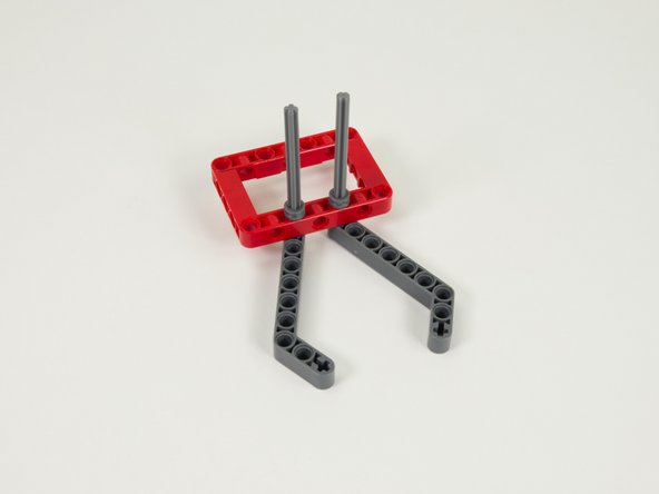
Place the servo (with attached beam) inside of the red frame.
-
The servo won't stay in place yet, but we'll add pins in the next step.
-
-
-
Place one long blue pin into the center hole of the frame on the beam side.
-
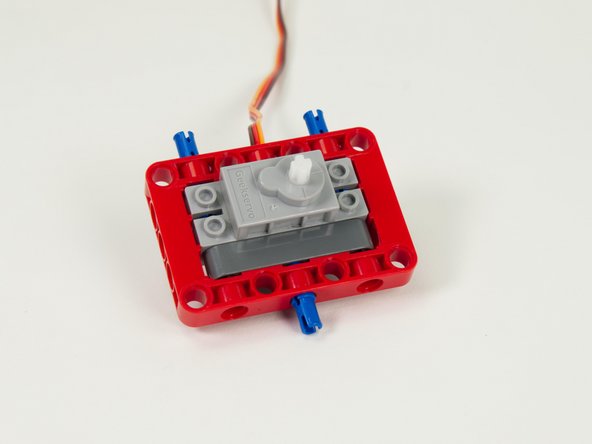
Place two long blue pins into the holes on the back of the red frame as shown.
-
The pins should go 2/3rds of the way in, and 1/3rd of the pin should stick out from the frame.
-
-
-
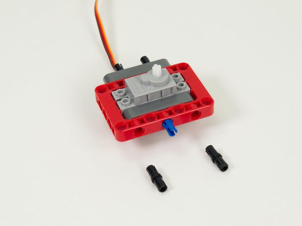
Add a gray 5 beam to the two pins on the back of the frame.
-
-
-
Add two black pins to the gray 5 beam on the back of the assembly.
-
These two pins will be used to mount the Gripper to the Rover in Step 24.
-
-
-
Add two pins to the front of the frame piece as shown.
-
-
-
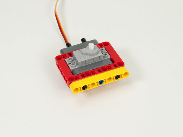
Add a yellow 7 beam to the pins on the front of the assembly.
-
-
-
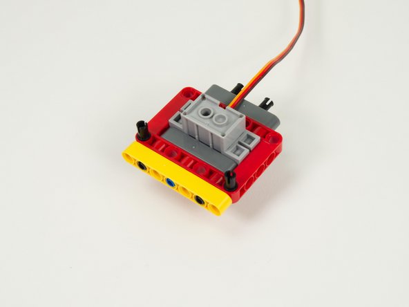
Flip the assembly over so the servo is facing down. (This is the direction it will be in when the Gripper is completed.)
-
Add two black pins to the frame as shown.
-
-
-
Add another yellow 7 hole beam to the red frame using the two black pins added in the previous step.
-
-
-
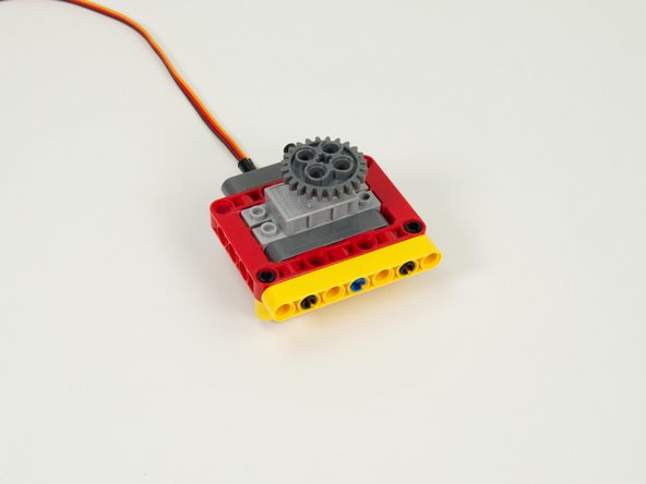
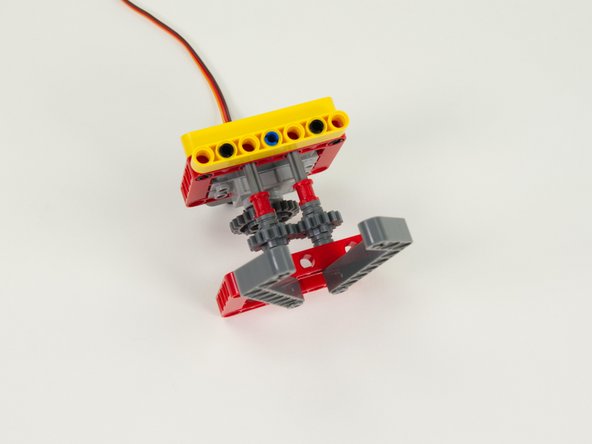
Attach the large gray gear to the servo by pressing it into place.
-
-
-
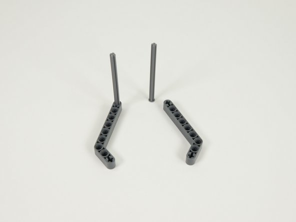
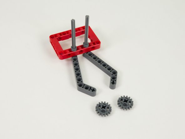
Start the assembly of the "fingers" by sliding the axles into the end of the gray angled beams as shown.
-
Make sure you use the axles with stoppers on the end.
-
-
-
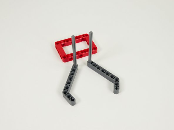
Slide the axles into the second red frame as shown.
-
-
-
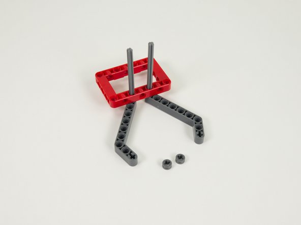
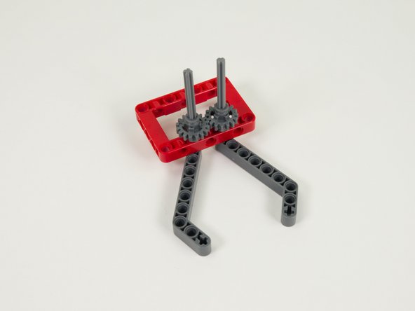
Slide two gray half bushings onto the tops of the axles and press down against the red frame.
-
-
-
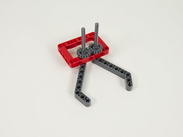
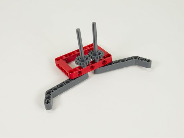
Press the two small gray gears down the axles so the are pressing against the half bushings.
-
The two gears should mesh together so that when you move one finger, the other one mirrors the movement so they can open and close.
-
-
-
Press two more gray half bushings down onto the axles so they are touching the gears.
-
-
-
Press two red (full size) bushings down the axles so they are pressing against the half bushing added in the previous step.
-
-
-
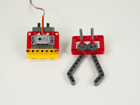
We'll now assemble the two halves of the Gripper together.
-
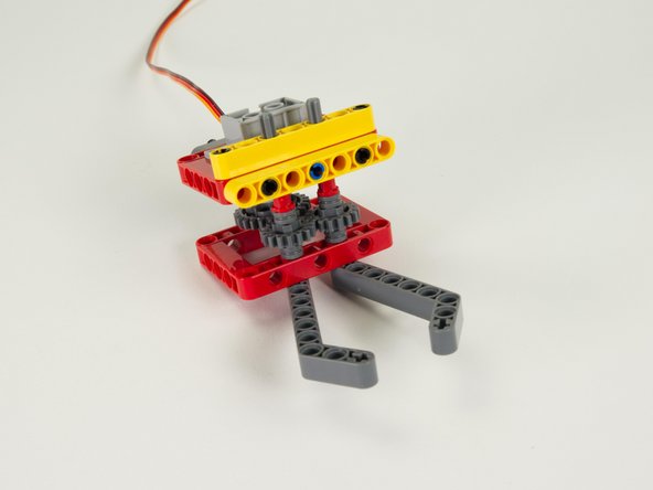
Slide the axles from the bottom part into the holes of the frame on the top part. (The red frames should align.)
-
Make sure the large gear on the servo meshes properly with one of the small gears on the bottom assembly.
-
-
-
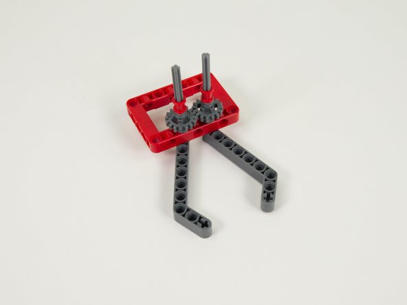
Add two red bushings to the top of the axles that are sticking out of the top of the assembly. These should hold the axles in place so they cannot fall out.
-
-
-
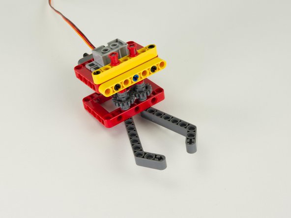
Now is a good time to check that the gears are all aligned and mesh properly.
-
The large gear on the servo should mesh with one of the gears on the finger assembly...
-
And the two small gears on the finger assembly should mesh with each other.
-
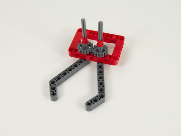
Note that the fingers will not be exactly symmetrical due to how the gears mesh together. This will not affect the performance of the Gripper.
-
-
-
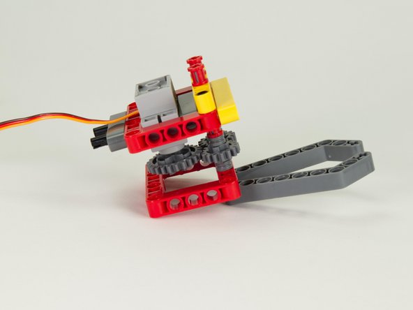
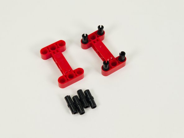
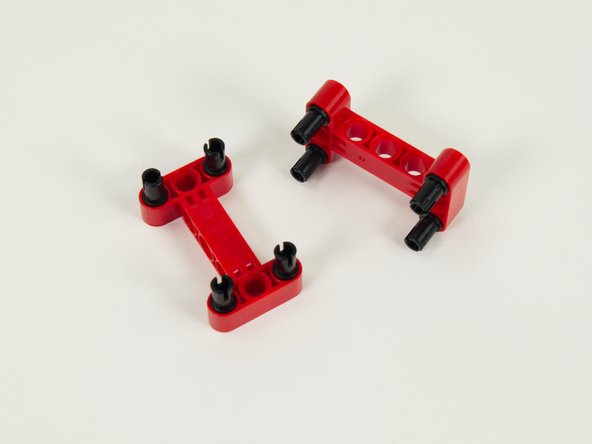
Insert four black pins into each of the red I-shaped beams as shown.
-
-
-
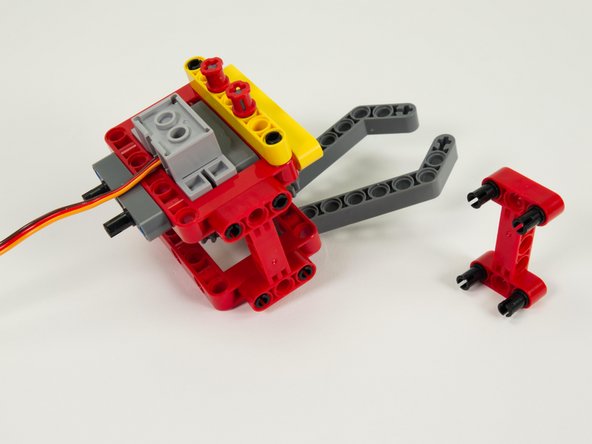
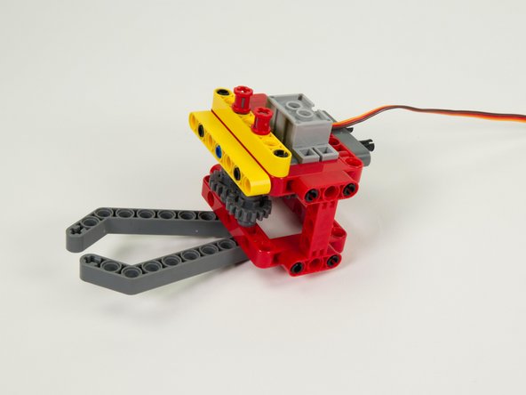
Add the red I beams to both sides of the Gripper. These will provide stability for the assembly while in operation.
-
Note: If you ever have to make adjustments to the gears you can usually do so by just removing these two I beams.
-
-
-
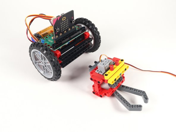
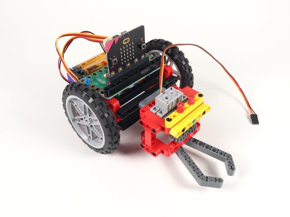
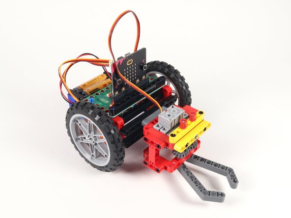
With our Gripper complete we can easily attach it to the front of the Rover.
-
Just use the pins sticking out the back of the Gripper to attach to the front beam on the Rover.
-
-
-
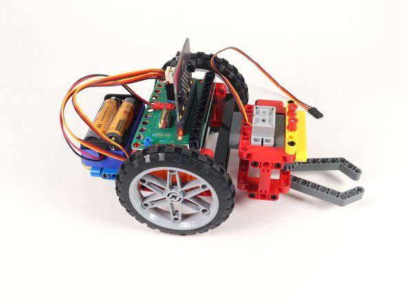
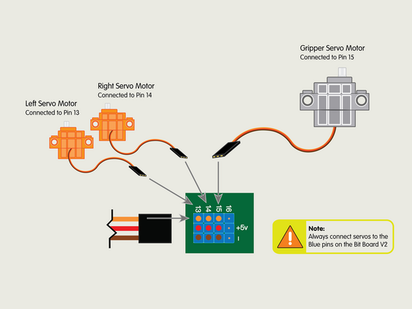
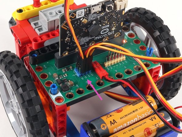
Plug the servo connector into the row for Pin 15. The orange wire should go to the pin closest to the 15 on the board, the red wire goes into the +5v row, and the brown wire goes into the - row, which is ground.
-
All servos should go to the 5V Blue Pins.
-
-
-
If you've never used a micro:bit before you'll want to check out this guide: Bit Board V2 Setup and Use
-
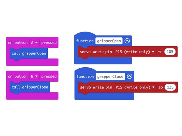
We're going to load the following code for our Gripper Test Code program: https://makecode.microbit.org/_YP926Vh66...
-
This code is very simple, and is just meant to test the Gripper.
-
When you press the A button on the front of the micro:bit it should open the Gripper fingers.
-
When you press the B button on the front of the micro:bit it should close the Gripper fingers.
-
-
-
To test the Gripper power the Bit Board with the battery pack.
-
If the angles of the fingers are not right check the next step to make adjustments.
-
-
-
If open and close don't move the fingers to the correct positions you have two options to adjust things.
-
You can remove the large gear from the servo shaft/axle and rotate the fingers, then put the gear back in place and try again.
-
If needed, you can remove the I beams added in Step 23 if it's difficult to get to the gear to remove it.
-
Alternately, you can also opt to adjust the angles in the code, and then reload the new code and try again.
-
Typically you want the close position to have the fingers just about touching, with a small gap. This helps prevent the servo from overworking and applying too much pressure.
-
For the open position the fingers should be open about 180 degrees from each other.
-