Introduction
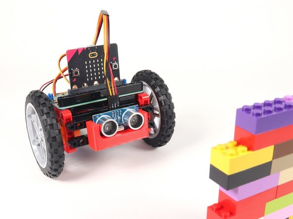
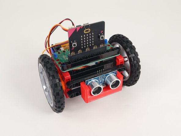
If you've built our Rover Main Body you can add an Ultrasonic Distance Sensor so your Rover can avoid running into things.
Video Overview
Featured Document
-
-
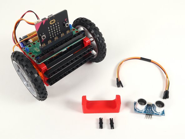
Along with your Rover you'll need a few other components.
-
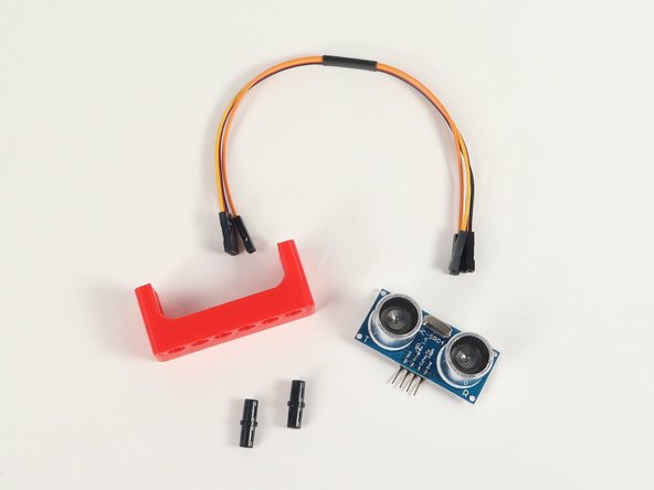
One Ultrasonic Distance Sensor
-
Distance Sensor Holder with Holes
-
Two pins
-
Crazy Circuits Ribbon Cables
-
-
-
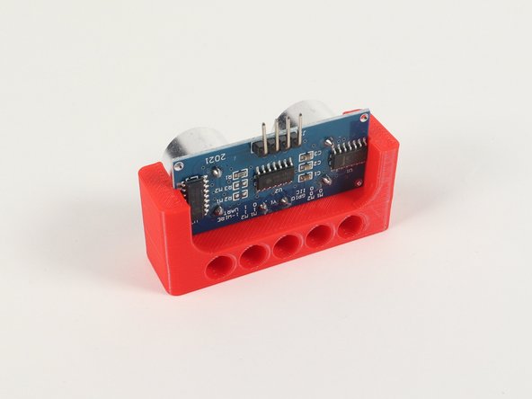
The Distance Sensor Holder with Holes is a 3D printed part that is LEGO Technic compatible.
-
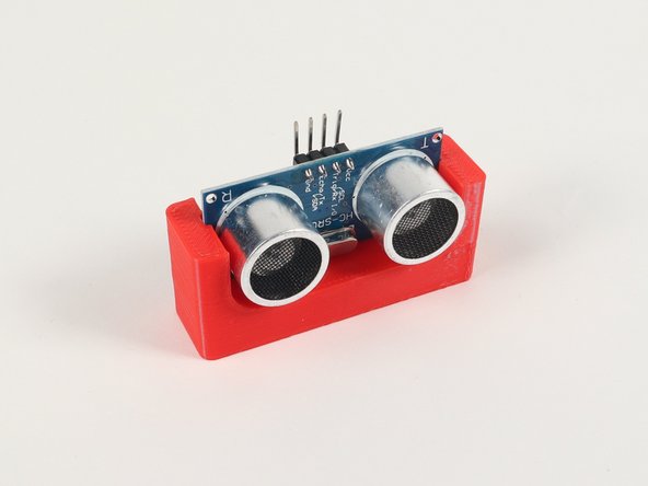
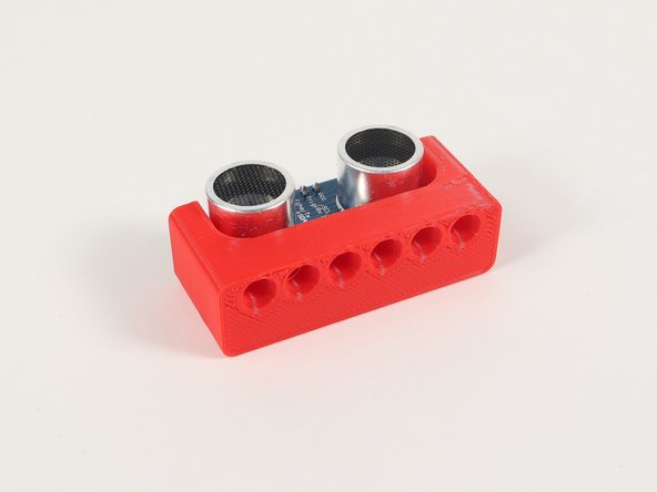
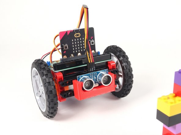
The Ultrasonic Distance Sensor slides into two slots on the Holder so the four connection pins on the Sensor are at the top so we can easily add jumper wires.
-
-
-
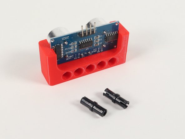
The Distance Sensor Holder has mounting holes on the bottom as well as the back side.
-
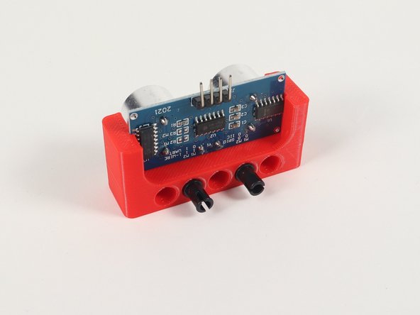
To mount it to the front of the Rover we'll use two pins placed into holes on the back.
-
Slide the Distance Sensor Holder with pins into the lower beam on the front of the Rover as shown.
-
-
-
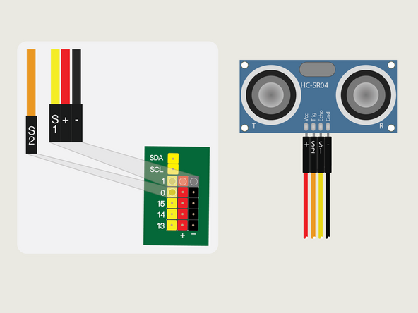
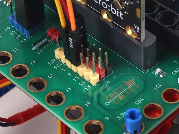
Plug the three-wire connector of the Crazy Circuits Ribbon Cable into the row with Pin 1 on the Bit Board. The wire colors should match the pin header colors, with S1 (yellow) going to the yellow pin.
-
Next, plug S2 (orange) into Pin 0. (S2 is separated from the three-wire connector to allow you to plug it into another row.)
-
Now we can plug the other end of the Crazy Circuits Ribbon Cable (with each wire independent) into the pins on the Distance Sensor.
-
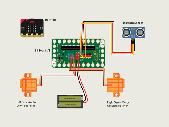
Plug + (red) into VCC; S2 (orange) into TRIG; S1 (yellow) into ECHO; and - (black) into GND.
-
-
-
If you've never used a micro:bit before you'll want to check out this guide: Bit Board V2 Setup and Use
-
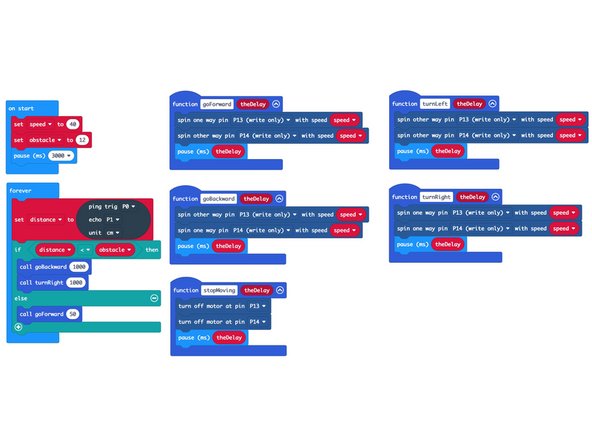
We're going to load the following code for our Rover Obstacle Avoidance program: https://makecode.microbit.org/_4wHXzvEVj...
-
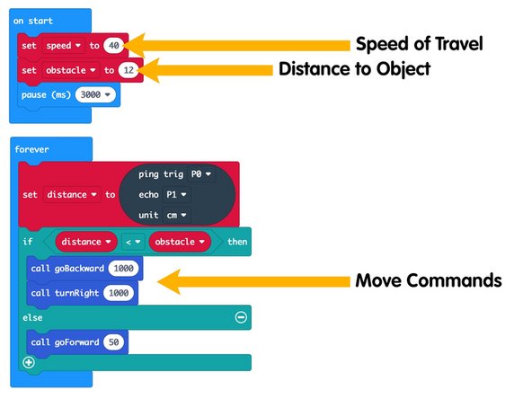
Note! We've put in a 3 second delay. It's the pause block in the on start section. This is so your Rover doesn't roll away as soon as the code is uploaded (or a battery pack is connected).
-
We recommend you remove the micro:bit from the Bit Board for programming, then after the code is loaded disconnect the USB cable and place the micro:bit into the Bit Board.
-
The 3 second delay is there so that when you plug in the battery pack you have a few seconds to put the Rover down on the floor before it starts moving.
-
-
-
Let's test the Rover with the Distance Sensor!
-
Remember, when you plug in the battery pack the Rover will wait 3 seconds before it starts moving.
-
Our code tells the Rover to check the Distance Sensor to see if an obstacle is in front of it. If there is an obstacle the Rover will move backwards, then turn right. Else the Rover will move forward.
-
The Distance Sensor will keep looking for something in front of it, and move forward when it can, and backup and then turn right, when it cannot move forward.
-
-
-
While you probably don't want to change any of the functions in the code (goForward, goBackward, turnLeft, turnRight, and stopMoving) there are a few things you can change.
-
Speed of Travel will affect how fast the Rover moves. We do not recommend setting this higher than 50. (See note below.)
-
Distance to Object is how many Centimeters away an object is from the sensor. You can adjust this number higher or lower.
-
The Speed of Travel and the Distance to Object affect each other. If the Rover is moving too fast and the distance to an object is a small amount the Rover might hit the object before it can react and avoid it! Experimenting with values is a great way to experiment.
-
Finally, the Move Commands could be adjusted as well. Right now when an object is detected the Rover will backup for one second (1000 ms) and turn right for one second (1000 ms). You could change these times to see how it affects the Rover. You could also choose to turn left instead of right by calling the turnLeft function.
-
If you're up for a challenge you could try to make the Rover go around an object. What would the code for that look like?
-
Attached Documents
