
Introduction
Build a remote control with two thumbsticks to control your Rover. The left thumbstick controls the left wheel (forward & backward) and the right thumbstick controls the right wheel. You can drive forward, reverse, or spin in either direction.
You can also manipulate the Gripper using the built-in buttons on each thumbstick to open and close the fingers. We've also made it easy to change the speed of the Rover using the A and B buttons on the micro:bit
If you want a more bare-bones remote check out our Rover Simple Remote or Rover Bluetooth Control
Video Overview
-
-
If you've built the Basic Rover Main Body and you want a full-featured remote control this guide will show you how to build one.
-
We'll load new code onto the Rover's micro:bit so it can act as a receiver (RX), and we'll load code onto the second micro:bit so it can work as a transmitter (TX).
-
Our remote will control the left and right wheels independently, which will allow the rover to move forward, backwards, and turn left and right. (And spin around in circles!)
-
Since the thumbsticks have built-in buttons (that are activated when you press down) we'll use those to control the Rover Gripper if you have it attached.
-
We've added one more feature. You can change the speed of the Rover by using the remote. By default it will start at 50% speed but you can decrease or increase this.
-
Just press the A button on the Remote Control micro:bit to slow it down. (One press lowers 10% each time.)
-
Pressing the B button will inversely increase the speed by 10% each time.
-
-
-
We'll begin by assembling the Rover Remote. You should only have to do this once when you first unpack your kit.
-
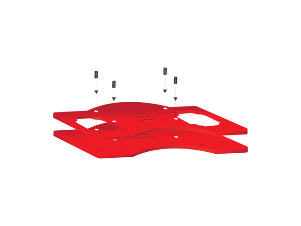
Begin by stacking the two plastic plates as shown below. Use four black pins to connect them. The plate with two large cutouts should be on top
-
-
-
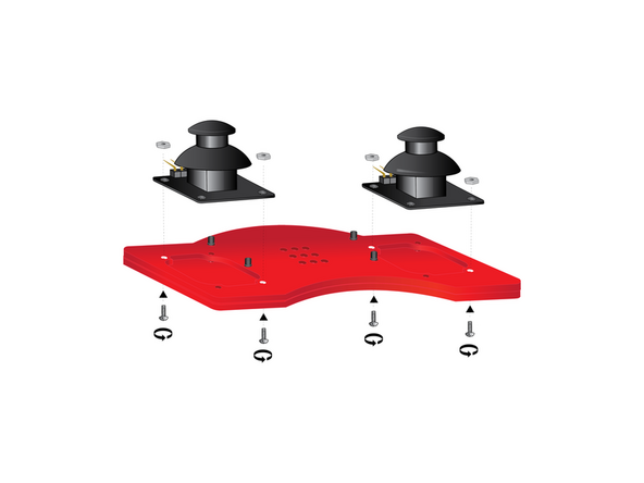
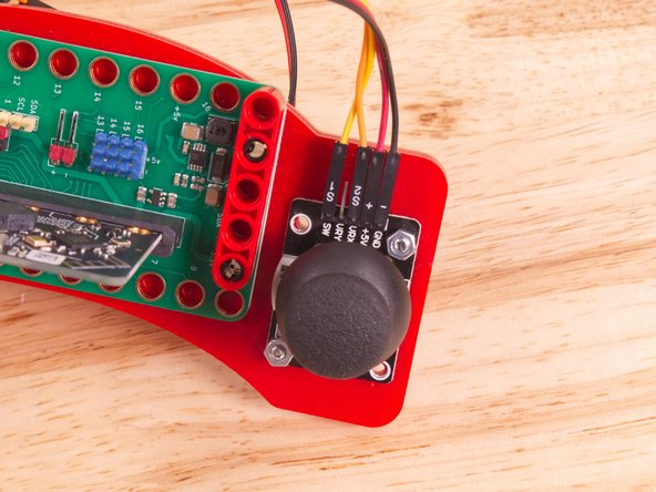
Position, and orient your two thumbsticks as shown. Secure each with two screws and nuts (nuts on top); hand-tightened at diagonally opposite corners.
-
-
-
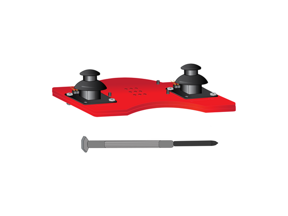
Use a small Phillips Head Screwdriver to tighten each of the four screws holding the thumbsticks in place. Do not over-tighten.
-
-
-
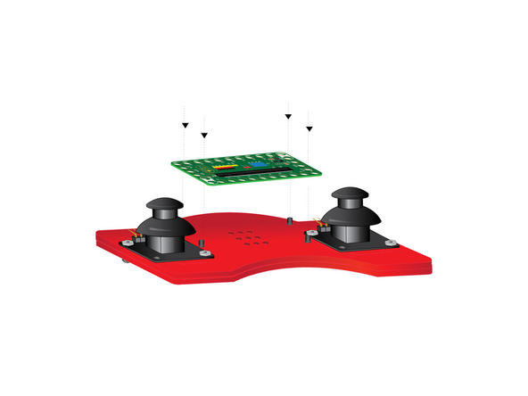
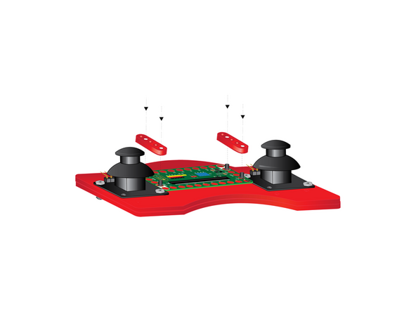
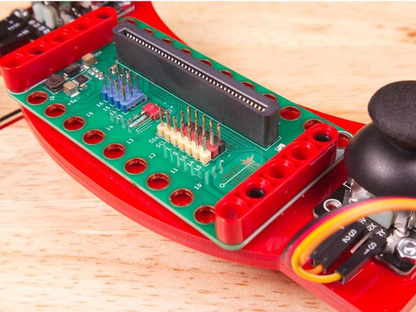
Orient your Bit Board so that the long side with clustered pins faces the curved bump out and the black micro:bit slot faces the inward curve. Press into place atop the four black pins.
-
-
-
Use the (2) five-hole beams to secure the Bit Board in place by pressing them onto the four black pins. Use the beam holes shown in white.
-
-
-
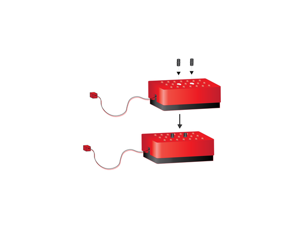
Press the two remaining black pins into place where shown in white on the grid of holes on the bottom of the battery pack.
-
-
-
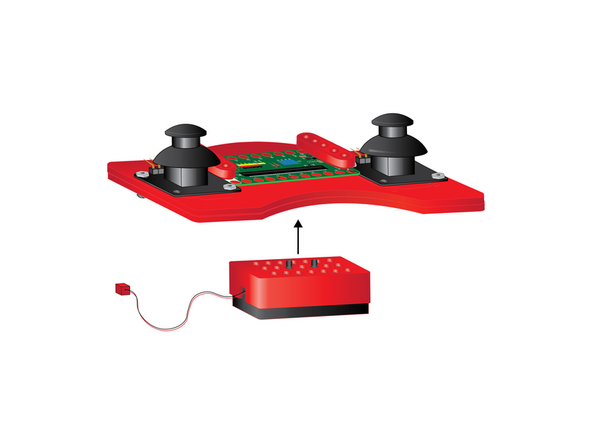
Attach the battery pack by pressing the exposed ends of the pins in the battery pack into the grid of holes on the underside of the remote body.
-
-
-
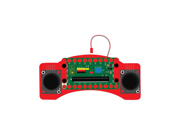
Your Remote is now assembled.
-
We won't need to plug in the Battery Pack until after we load the code and are ready to test it out.
-
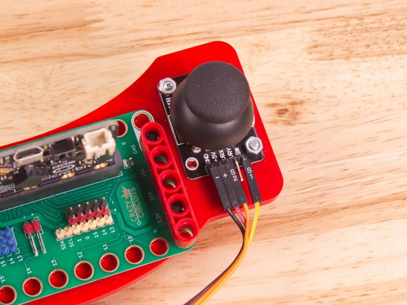
In the next steps we'll connect the Thumbsticks to the Bit Board.
-
-
-
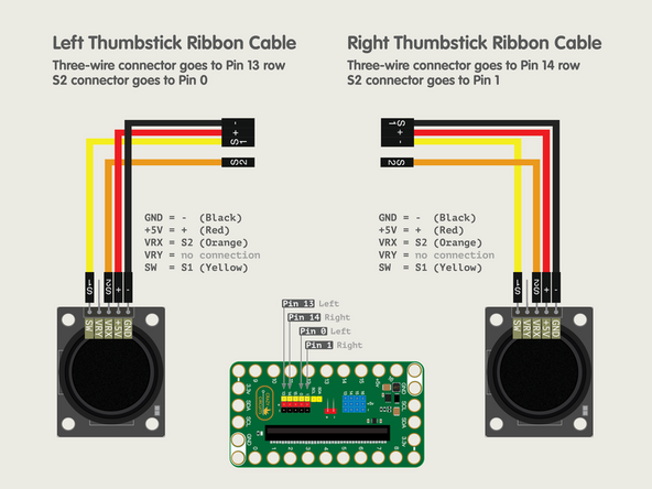
The Crazy Circuits Ribbon Cable has two different ends. One end has a black connector with three wires going into it (-, +, and S1) and a single black connector with one wire going into it (S2).
-
The other end has four single connectors which break out each wire individually. This is the end we'll connect to the Thumbsticks.
-
Connect the black wire (-) to GND on the Thumbstick.
-
Connect the red wire (+) to +5V on the Thumbstick.
-
Connect the orange wire (S2) to VRX on the Thumbstick.
-
Finally, connect the yellow wire (S1) to SW on the Thumbstick.
-
Once you've connected the wires to one Thumbstick, do the same thing to the other Thumbstick.
-
If both Thumbsticks are connected as shown we can move on to connecting the wires to the Bit Board!
-
-
-
We’ve broken this down into four step, in the order that is easiest to assemble.
-
Note: We recommend you remove the micro:bit from the Bit Board for this part, as it can make it easier to connect the wires.
-
-
-
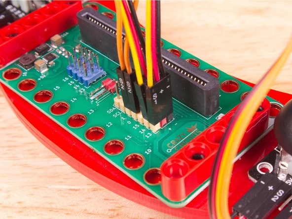
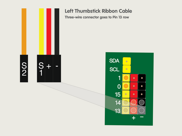
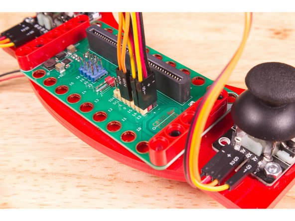
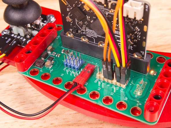
Start by connecting the Left Thumbstick, with the 3-Wire Connector plugging into Pin 13.
-
The yellow wire (S1) goes into the yellow Pin 13.
-
The red wire (+) goes into the red pin next to Pin 13...
-
And the black wire (-) goes into the black pin next to that.
-
-
-
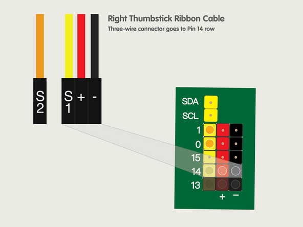
Next we'll connecting the Right Thumbstick, with the 3-Wire Connector plugging into Pin 14 this time.
-
The yellow wire (S1) goes into the yellow Pin 14.
-
The red wire (+) goes into the red pin next to Pin 14...
-
And the black wire (-) goes into the black pin next to that.
-
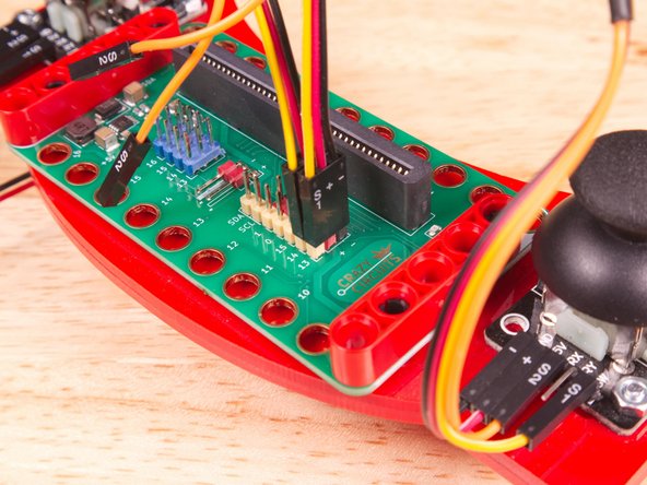
You should now have both of the 3-Wire Connectors plugged in, with the left going to Pin 13 and the right going to Pin 14.
-
-
-
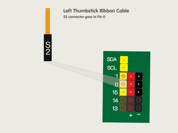
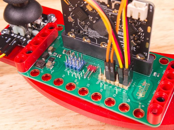
Back to the Left Thumbstick now...
-
The orange wire (S2) goes into the yellow Pin 0.
-
Pin 0 is an analog pin. We'll plug our Left Thumbstick in here as it will be sending analog data to the micro:bit
-
-
-
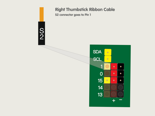
Finally, we'll finish with the Right Thumbstick...
-
The orange wire (S2) goes into the yellow Pin 1.
-
Pin 1 is an analog pin. We'll plug our Right Thumbstick in here as it will be sending analog data to the micro:bit
-
-
-
Once you've got all the wiring completed you can plug the micro:bit back in so we can load the code!
-
You can plug in the battery pack now, or wait until after you load the code.
-
-
-
If you've never used a micro:bit before you'll want to check out this guide: Bit Board V2 Setup and Use
-
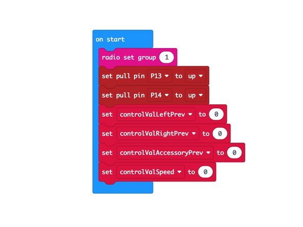
Let's load the code onto the Remote's micro:bit so it can function as a transmitter and send control signals to the micro:bit on the Rover.
-
Load the following code: Rover Thumb Remote TX program: https://makecode.microbit.org/_afEWzu5TX...
-
Note that we've set the radio group to 1. You can choose any number you want as long as the two micro:bits use the same number. For a classroom setting with multiple pairs you'll want each set to have a different number.
-
The TX stands for "Transmitter". For the code on the other micro:bit you'll see RX which stands for "Receiver".
-
-
-
If you've never used a micro:bit before you'll want to check out this guide: Bit Board V2 Setup and Use
-
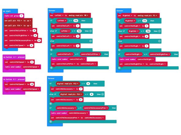
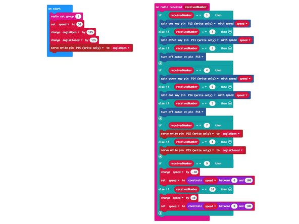
We're going to load the following code for our Rover Thumb Remote RX program: https://makecode.microbit.org/_T3bLW80qH...
-
Once you load the code it won't do anything. Since the code turns the micro:bit into a receiver it will wait until a transmitter sends data before it does something.
-
If you look at the code you'll notice the numbers 1 through 3, and 4 through 6, which we referenced in Step 1. Those are the numbers the transmitter will send to the receiver.
-
You may also notice the numbers 7 and 8, which are used to control the Gripper if you have it attached to your Rover.
-
Finally numbers 9 and 10 are used to change the speed of the Rover.
-
-
-
Once you've got code loaded on both micro:bits you can test using the remote control with your Rover.
-
The left thumbstick should make the left wheel turn, and the right joystick should make the right wheel turn.
-
Note that we consider the "left" wheel to be the one on your left side if you were standing behind the Rover, not facing the Rover.
-
The thumbsticks are also buttons that can be pressed. Pressing each should open and close the fingers of the Gripper.
-
If you want the Rover to move slower or faster press the A or B button on the micro:bit located on the Remote Control.
-
-
-
If you have issues getting the Remote to control the Rover we've written code to test the components and wiring of the Remote.
-
We're going to load the following code for our Thumbstick Remote Tester program: https://makecode.microbit.org/_3iYMChX7y...
-
Once the code is loaded it should behave like the Remote shown in the video.
-
The left thumbstick should move a pixel on the LED matrix on the left side up and down when you move the thumbstick, matching the movement direction.
-
You should see the same behavior on the right side of the LED matrix when you use the right thumbstick. (You can also test the button presses of each thumbstick)
-
Note: Don't worry if the pixel is not centered when you release the thumbstick. This is due to mapping a large scale onto a small scale.
-
If you are not seeing this behavior please double check your wiring, starting at Step 10.
-
If everything seems to work properly, your Remote is wired correctly and the thumbsticks are working as intended. You can now go back to Step 17 and reload the code for the Remote.
-


Attached Documents
