
Introduction
Explore the micro:bit's built-in sensors by connecting a 7 Segment Display to show numerical data.
This is the abbreviated version of our full Sensor Showcase. The full version uses an Ultrasonic Distance Sensor and also uses the built-in compass found on the micro:bit.
(This version does not use the Ultrasonic Distance Sensor and does not use the compass so no calibration is needed after loading the HEX file.)
Featured Document
-
-
The micro:bit has a number of built-in sensors which we'll explore with our Sensor Showcase code.
-
We'll take measurements based around the follow sensors built into the micro:bit: Temperature, Light Level, Sound Level, Acceleration, and Magnetic Force.
-
For each of the sensors we'll use a 7 Segment Display connected to the Bit Board to show numerical data from the sensor.
-
You'll want some sort of magnet for testing, and a flashlight or phone on-hand as well.
-
-
-
If you've never used a micro:bit before you'll want to check out this guide: Bit Board V2 Setup and Use
-
Note we recommend a micro:bit V2 (or higher) as the V1 lacks the microphone and speaker.
-
You can use a Bit Board V1 or later for this project.
-
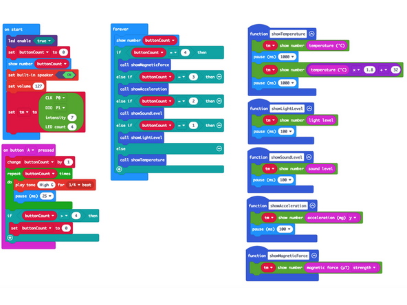
We're going to load the following code for our Sensor Showcase Abbreviated program: https://makecode.microbit.org/_0iALyoCfc...
-
-
-
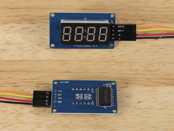
We'll add the 7 Segment Display by using a Crazy Circuits Ribbon Cable. Since each wire is labeled (and color coded) it's easy to make the connections.
-
If you don't have a Crazy Circuits Ribbon Cable any Female/Female jumper wires will work as long as you make all of the connections properly.
-
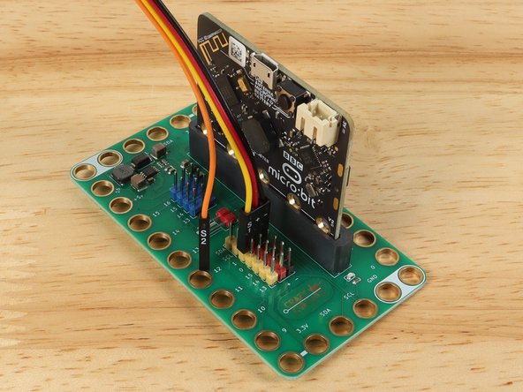
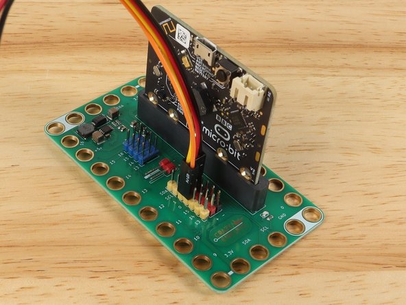
Plug the large connector (with three wires) into the Bit Board, so S1 aligns with Pin 1. This will put + (the Red wire) into + (Positive) and - (the Black wire) into - (Negative) or GND.
-
This leaves S2 not connected, so we'll plug that into Pin 0 on the Bit Board.
-
Once the wires are connected to the Bit Board we can add the 7 Segment Display.
-
-
-
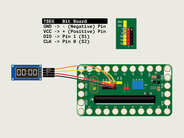
The 7 Segment Display has four pins. We'll connect the - wire to GND, the + wire to VCC, the S1 wire to DIO and the S2 wire to CLK.
-
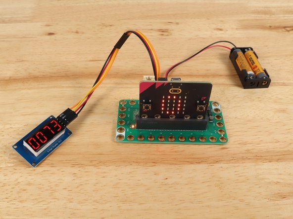
With the 7 Segment Display connected we're ready to start sensing!
-
-
-
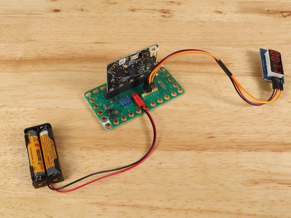
While testing various sensors you'll be moving the Bit Board and micro:bit around, so it may be easier to use the battery pack rather than the USB cable to power the circuit. (Though either will work just fine.)
-
-
-
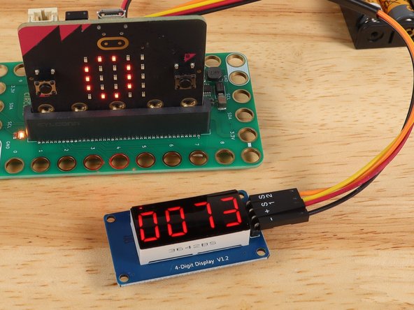
Now that we've got the code loaded and the 7 Segment Display connected we can walk through the various sensor examples.
-
There are 5 modes you can cycle through. When you start up the micro:bit it will be on “0”.
-
The buit-in LED matrix on the micro:bit will show which mode you are in. (0 through 4)
-
To go to the next mode press the "A" button on the micro:bit
-
-
-
The display will show the temperature, alternating between Fahrenheit and Celcius every second.
-
If you hold the micro:bit so your finger can press against the processor you may see the temperature rise.
-
The processor is the black square on the back of the board behind the "B" button.
-
-
-
The display will show the light level with a value between 0 (dark) and 255 (light).
-
You can use a flashlight (your phone's flashlight feature works great!) to see the values change. Just shine it at the front of the micro:bit and move it closer and farther away.
-
You can cover the micro:bit with your hand and it will probably go to zero (or very close) in most situations.
-
-
-
The display will show the sound level with a value between 0 (quiet) and 255 (loud).
-
Try clapping or whistling in front of the micro:bit to see the values change.
-
If you have a tone generator app on your phone you can adjust the frequency and volume to see how the values might change.
-
Depending on your age and hearing abilities you may be able to play tones that the micro:bit can hear but you cannot!
-
We've used Tone Generator (for iPhone and Android) with good results.
-
-
-
The display will show the angle of the micro:bit with a value between -1023 and 1023.
-
Actually, -999 is the lowest value you will see on the 7 Segment Display since the minus sign takes up the first digit position.
-
Tilt the micro:bit to the left, and to the right, and you will see the values change.
-
When tilted 90 degrees to the right or left the value should be near zero.
-
When the micro:bit and Bit Board are sitting flat on the table the value should be very close to 1024.
-
-
-
The display will show a value relative to the magnetic field it can detect.
-
On our workbench we saw a start value of 45 and a high value of about 3100 using a single ceramic magnet.
-
The results of this activity will vary depending on the magnet you use, but even with a small Neodymium magnet we saw great results, with a high of 2700.
-
Start with your magnet about 15 centimeters in front of the micro:bit and slowly move it closer. The value shown should increase the closer the magnet gets.
-
Tip: Try rotating the magnet to see how the magnetic field change and how that affects the value shown.
-
-
-
We hope this walk-through of the various sensors served as a good introduction to some of the things the micro:bit can sense.
-
The sensors can be valuable for exploring the world and recording data, and as you learn about each sensor, you might get ideas for programs you can create that use the sensors.
-
You could use the light sensing abilities to control a circuit with a flashlight, or sound sensing to play a series of beeps if the room gets too loud.
-
Integrating sensors into your projects can open a world of possibilities beyond switches and logic, and truly allows the micro:bit to react to the world.
-


Attached Documents
