
Introduction
Explore the micro:bit's built-in sensors by connecting a 7 Segment Display to show numerical data. We'll also connect an external Ultrasonic Distance Sensor to show how to measure distances.
If you want a version of this activity that is a bit simpler, check out our Sensor Showcase (Abbreviated) guide. It doesn't require the Ultrasonic Distance Sensor and skips the compass activity.
Video Overview
Featured Document
-
-
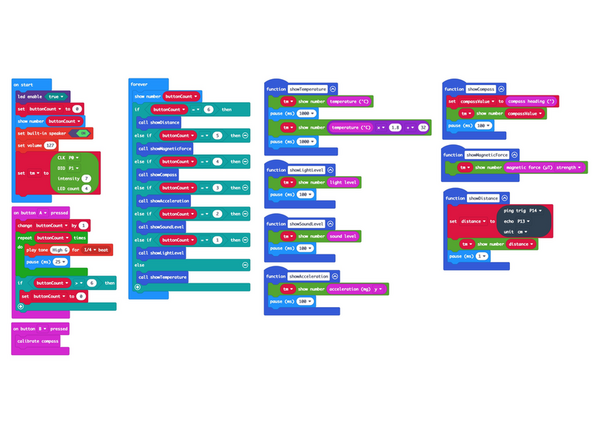
The micro:bit has a number of built-in sensors which we'll explore with our Sensor Showcase code.
-
We'll take measurements based around the follow sensors built into the micro:bit: Temperature, Light Level, Sound Level, Acceleration, Compass, and Magnetic Force.
-
We will also plug in an Ultrasonic Distance Sensor to show how external sensors can be used.
-
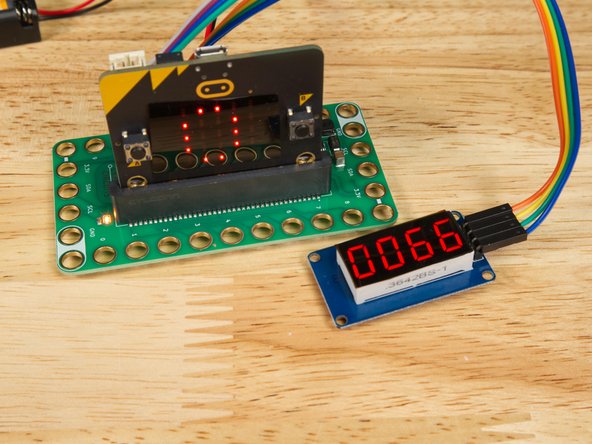
For each of the sensors we'll use a 7 Segment Display connected to the Bit Board to show numerical data from the sensor.
-
You'll want some sort of magnet for testing, and you may find it useful to have some tape, cardboard, and a flashlight or phone on-hand as well.
-
-
-
After the HEX file is loaded onto the micro:bit you will need to calibrate the compass. (We'll do this in Step 4.)
-
You typically only need to do this once when a new HEX file is loaded. It will remember the calibration when you restart the micro:bit.
-
-
-
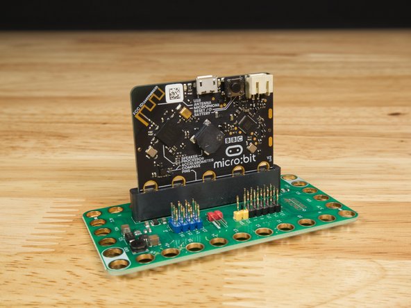
If you've never used a micro:bit before you'll want to check out this guide: Bit Board V1 Setup and Use
-
Note we recommend a micro:bit V2 (or higher) as the V1 lacks the microphone and speaker.
-
You can use a Bit Board V1 or later for this project.
-
We're going to load the following code for our Sensor Showcase program: https://makecode.microbit.org/_Te42Mi160...
-
-
-
To calibrate the compass after loading the HEX file wait for the micro:bit to start up and show a "0" on the built-in LED matrix.
-
Press the "B" button and the LED matrix will scroll the words "TILT TO FILL SCREEN".
-
You then need to keep tilting and rotating the micro:bit until all the of LEDs light up. (You can start the tilting while the words are still scrolling.)
-
When completed a smiley face will show on the LED matrix, then it will return to showing "0".
-
-
-
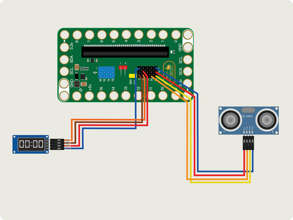
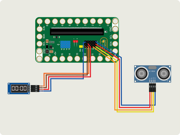
We'll add the 7 Segment Display by using four Female/Female jumper wires. Each pin of the display will connect to a pin on the Bit Board.
-
Plug the 7 Segment Display CLK into Pin 0, DIO into Pin 1, Vcc into the + (positive) column, and Gnd into the - (negative) column.
-
You can use any color wire you want, as long as they connect to the correct pin. It's common to use red for positive and black for negative but your circuit won't know what color the wires are. :)
-
The pins in the + (positive) column are all connected together and go to the 3.3v power supplied by the Bit Board.
-
The pins in the - (negative) column are all connected together and go to the common ground connection of the Bit Board.
-
-
-
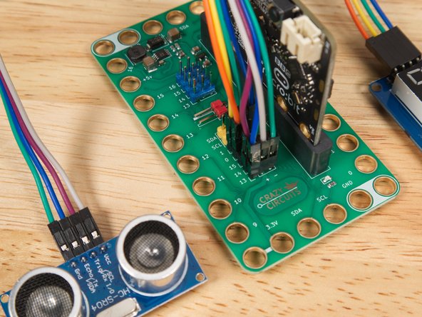
Next we'll add the Ultrasonic Distance Sensor by using four Female/Female jumper wires.
-
Plug the Distance Sensor Echo into Pin 13, Trig into Pin 14, Vcc into the + (positive) column, and Gnd into the - (negative) column.
-
(Again, you can use any color wire you want, as long as they connect to the correct pins.)
-
-
-
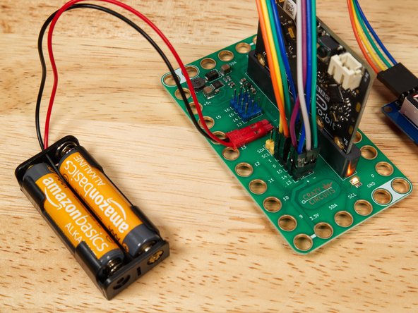
While testing various sensors you'll be moving the Bit Board and micro:bit around, so it may be easier to use the battery pack to power the circuit.
-
You can power your circuit using the USB cable that plug into the micro:bit, but it may get a bit awkward with some of the modes, such as the compass.
-
-
-
Now that we've got the code loaded, and the 7 Segment Display and Distance Sensor connected, we can walk through the various sensor examples.
-
There are 7 modes you can cycle through. When you start up the micro:bit it will be on “0”.
-
The buit-in LED matrix on the micro:bit will show which mode you are in. (0 through 6)
-
To go to the next mode press the "A" button on the micro:bit
-
Don't press "B" unless you want to re-calibrate the compass again!
-
-
-
The display will show the temperature, alternating between Fahrenheit and Celcius every second.
-
If you hold the micro:bit so your finger can press against the processor you may see the temperature rise.
-
The processor is the black square on the back of the board behind the "B" button.
-
-
-
The display will show the light level with a value between 0 (dark) and 255 (light).
-
You can use a flashlight (your phone's flashlight feature works great!) to see the values change. Just shine it at the front of the micro:bit and move it closer and farther away.
-
You can cover the micro:bit with your hand and it will probably go to zero (or very close) in most situations.
-
-
-
The display will show the sound level with a value between 0 (quiet) and 255 (loud).
-
Try clapping or whistling in front of the micro:bit to see the values change.
-
If you have a tone generator app on your phone you can adjust the frequency and volume to see how the values might change.
-
Depending on your age and hearing abilities you may be able to play tones that the micro:bit can hear but you cannot!
-
We've used Tone Generator (for iPhone and Android) with good results.
-
-
-
The display will show the angle of the micro:bit with a value between -1023 and 1023.
-
Actually, -999 is the lowest value you will see on the 7 Segment Display since the minus sign takes up the first digit position.
-
Tilt the micro:bit to the left, and to the right, and you will see the values change.
-
When tilted 90 degrees to the right or left the value should be near zero.
-
When the micro:bit and Bit Board are sitting flat on the table the value should be very close to 1024.
-
-
-
The compass will show a value between 0 and 360. (With 0 being North, 90 being East, 180 being South, and 270 being West.)
-
In our tests the compass was not extremely accurate. We ended up recalibrating the compass for better results.
-
We saw better results by tipping the Bit Board & micro:bit onto its back so the front of the micro:bit was facing towards the sky.
-
It may be helpful to place the micro:bit onto something flat like a book or a piece of cardboard, and then rotate that around in a circle.
-
Note that you should move the magnets you'll use in Mode 5 far away from the micro:bit as they can affect the compass readings.
-
-
-
The display will show a value relative to the magnetic field it can detect.
-
On our workbench we saw a start value of 45 and a high value of about 3100 using a single ceramic magnet.
-
The results of this activity will vary depending on the magnet you use, but even with a small Neodymium magnet we saw great results, with a high of 2700.
-
Start with your magnet about 15 centimeters in front of the micro:bit and slowly move it closer. The value shown should increase the closer the magnet gets.
-
Tip: Try rotating the magnet to see how the magnetic field change and how that affects the value shown.
-
-
-
Make sure you've connected the Distance Sensor as specified in Step 6.
-
Set the Distance Sensor so it is facing up towards the sky. It will probably show a number over 200, though it may jump around a bit.
-
Place your hand directly over the sensor about 50 centimeters above it, and slowly moved your hand towards the sensor.
-
You should see the values lower as your hand gets closer. If you have a ruler handy you can check that the centimeter value shown on the display approximately matches the distance.
-
-
-
We hope this walk-through of the various sensors served as a good introduction to some of the things the micro:bit can sense.
-
The sensors can be valuable for exploring the world and recording data, and as you learn about each sensor, you might get ideas for programs you can create that use the sensors.
-
You could use the light sensing abilities to control a circuit with a flashlight, or sound sensing to play a series of beeps if the room gets too loud.
-
Integrating sensors into your projects can open a world of possibilities beyond switches and logic, and truly allows the micro:bit to react to the world.
-


Attached Documents
