Introduction
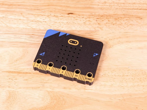
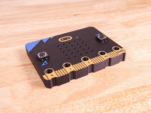
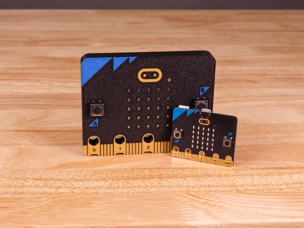
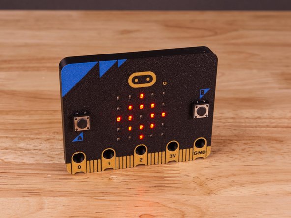
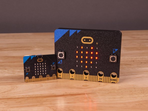
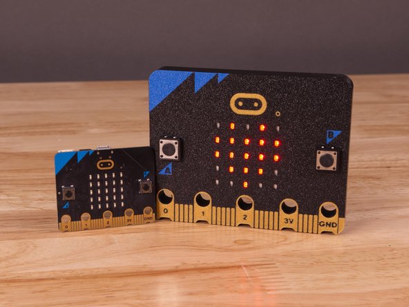
Make your own 3D Printed (Larger than Life!) Micro:Bit! Add some electronics to make it light up and display classic icons and simple animations.
Video Overview
-
-
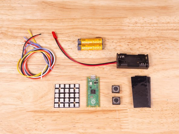
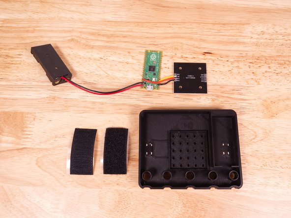
Let's start by looking at the parts we'll need. The crucial components here are the LED matrix, the microcontroller, wire, and the battery pack.
-
5x5 NeoPixel Matrix - This will be the face of our project. The tiny little LEDs that will light up to make our Large Micro:Bit look like a real Micro:Bit
-
Raspberry Pi Pico - This will be the brains of our project. We debated trying to fit an actual Micro:Bit into the Large Micro:Bit but eventually settled on a smaller more solder-friendly microcontroller.
-
We've also successfuly used a Seeed Studio XIAO board for this project. Any of the small microcontrollers that use an RP2040 chip are a good choice and you can easily drag & drop code just like with the Micro:Bit. Note: Make sure whatever board you use does not have the header pins already attached.
-
2AAA Battery Holder - We chose to use our own since we have a warehouse full of them. If you use a different one it should fit, otherwise you may need to carve down the sides just a bit.
-
Silicone Stranded Wire (24 Gauge) - We'll need some wire to connect the components. You can use any thin wire, but stranded wire is better than solid core wire for this, and we really prefer this silicone coated wire as it's the most flexible and easy to stuff into a tight space.
-
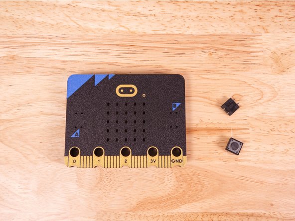
12x12x5mm Tactile PCB Push Buttons - These will attach to the Large Micro:Bit where the "A" and "B" buttons are on the front of the Micro:Bit. They are not functional but help make it look a little more realistic.
-
Hook & Loop with Adhesive Backing - This is another item we have in our warehouse, but any strip of adhesive backed hook and look should work just fine. We only need a small piece to hold the microcontroller in place. (We wanted the controller to be easily removable to load new code.)
-
-
-
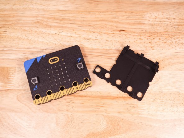
You will need to download and print the 3D Printed (Large) Micro:Bit files.
-
We used a Bambu Lab 3D Printer with an AMS unit. This allowed us to make a multi-color print for the front piece of the Micro:Bit. (Any other multi-color 3D printer should work just as well.)
-
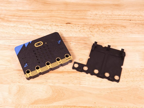
The colors we used were black, gold, and blue. The black matches the main body of the Miicro:Bit and the gold is used for the exposed copper connection points at the bottom edge and for the (touch) logo.
-
While we used blue, you can try using any other color you'd like, but we found blue give the best print results since it's aleady a daker color and the black doesn't bleed through like it does for yellow or other lighter colors.
-
If you do not have multi-color print capabilities you could 3D print the front in black and either (2D/paper) print out and attach the color elements, or perhaps paint them on. It doesn't have to be perfect!
-
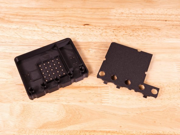
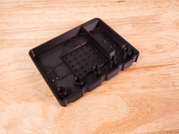
The back piece, which mostly just covers the electronic components and holds the wires in place, should be printed in black.
-
We recommend using a textured build plate and printing face down.
-
-
-
Note! Soldering can be dangerous since a high-heat iron is involved. But if done properly it can be a safe activity and valuable skill.
-
We're going to assume you have a soldering iron and know how to use it. If not, it's a lesson beyond the scope of this guide. If you need to learn check out the Adafruit Guide To Excellent Soldering or this awesome Soldering is Easy comic.
-
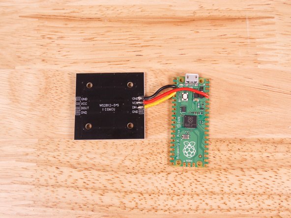
To begin we're going to connect three wires to the LED Matrix. We need three wires cut about 50mm long, with the insulation stripped off the ends. There should be about 3mm of exposed wire.
-
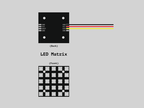
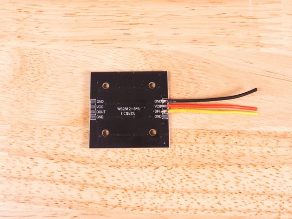
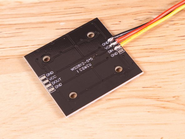
Solder the yellow, red, and black wires to the LED Matrix as shown. Since you need to solder to pads instead of through-holes, this is the trickiest part.
-
I find that using some painters tape to hold the wires in place can help. You can also add some solder to the pad and then heat up the wire on top of the solder glob and press it into place.
-
Check your work! Make sure you don't have an solder or stray wire making contact where it should not.
-
This is the most difficult part of the entire project. Through-hole soldering isn't too difficult, but soldering to pads can be a challenge! Especially for beginners. If you don't get it right just keep trying. You can heat the solder up, pull the wires off, cut, strip, and try again.
-
-
-
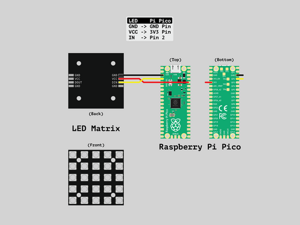
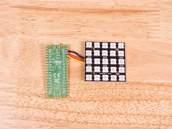
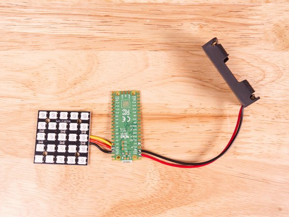
Now we can solder the black, yellow, and red wires to the microcontroller. We'll be soldering through-hole this time, which is a bit easier than the pad soldering in the previous step.
-
The red wire goes to the 3V3 pin.
-
The black wire goes to a GND pin. (We used the one right next to Pin GP2.)
-
The yellow wire goes to the pin labeled GP2.
-
The black and yellow wires can be cut shorter to save space for the wiring inside the case.
-
Make sure to double check the position for each wire. Note that the pin labels are on the bottom of the Pi Pico.
-
-
-
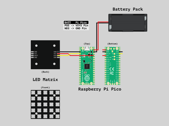
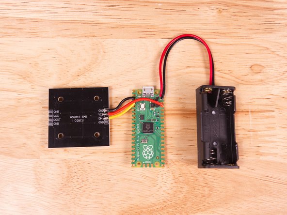
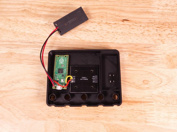
We'll now connect our 2AAA Battery Pack. (Make sure you do not have the batteries installed yet!)
-
Solder the red wire to the VSYS pin hole. Note that it is the second hole from the end. (The labels on the bottom are not perfectly aligned due to the mounting holes.)
-
Solder the black wire to the GND pin hole right next to VSYS. The GND pin hole is the third from the end.
-
Soldering is all done!
-
-
-
We're going to load the code now to make sure everything works! If things do not work we want to know about it before we finish the assembly.
-
You can find the code in our GitHub repository: https://github.com/BrownDogGadgets/Crazy...
-
While you'll find the Arduino sketch (BDG_Large_MicroBit.ino) in the repo, you will also find BDG_Large_MicroBit.ino.uf2 and BDG_Large_MicroBit_Flipped.ino.uf2, which is firmware you can load without having to deal with code.
-
You'll need to hold down the small white Reset button on the Pi Pico while plugging in the USB cable. After it is plugged wait a few seconds and release the button. You should see a new USB drive named RPI-RP2 appear on your computer.
-
You can now copy the BDG_Large_MicroBit.ino.uf2 file to the RPI-RP2 drive and it should eject.
-
-
-
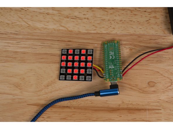
The code should now be running! Do you see the LED matrix lighting up red and showing icons? If not, check all of your wiring. (Note that you don't need the batteries yet, as the USB power from your computer will run things just fine.)
-
Why do the icons appear upside down!? We've found that some LED panels are right side up and some are upside down, so if yours appears to be upside down just install the "flipped" firmware.
-
If everything is good we can finish the assembly.
-
-
-
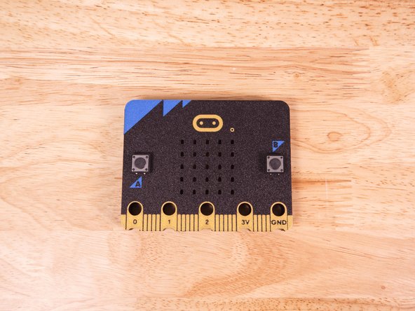
Insert the legs of the buttons through the slots for the A and B buttons on the 3D Printed Micro:Bit.
-
-
-
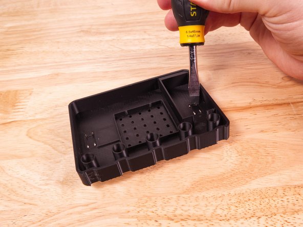
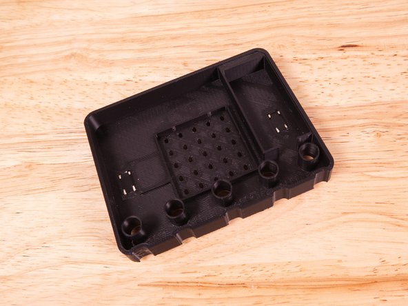
Flip the 3D Printed Micro:Bit over and you'll see the legs of the buttons sticking up. We're going to bend them flat so the buttons don't fall out.
-
We used a slotted screwdriver to press the legs flat. They bend easily but you'll still probably need a tool do to it. (A pen or other writing implement could also work.)
-
Once all eight legs are bent flat we can move on.
-
-
-
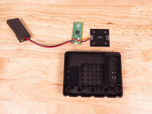
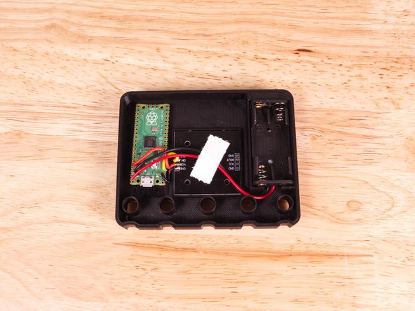
We're ready to start getting our electronics in place. We'll start by adding some hook & loop, placing it over two of the legs of the B button. (Which is on the left side when the Micro:Bit is face down.)
-
We trimmed down the loop piece a bit. It doesn't need to be huge.
-
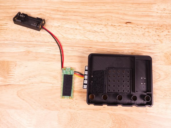
We also trimmed down the hook piece and stuck it to the back of the Pi Pico microcontroller so we can stick it down to the loop piece.
-
-
-
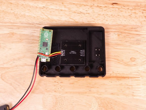
The LED matrix should just snap into place.
-
Make sure you've got it the right way up! (If you get it wrong, turn it around or upload the other version of the firmware.)
-
If the matrix does not stay in place you can always add some tape or hot glue.
-
-
-
Stick the Pi Pico microcontroller down with the hook & loop.
-
When you get to Step 14 you may need to shift the microcontroller around so the cover fits properly. This is easy to do with the hook & loop.
-
-
-
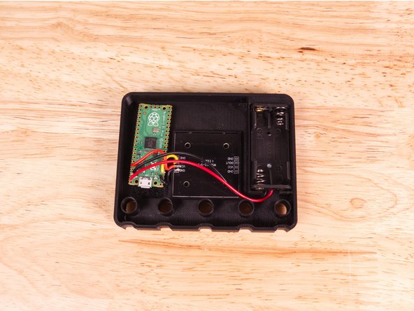
The 2AAA Battery Pack goes into the pocket on the opposite side of the microcontroller.
-
Make sure to route the wires as shown. As with the microcontroller, you may need to make adjustments to the wires for the back cover to fit.
-
The Battery Pack can be held down with tape or hot glue. If you do hot glue it test with batteries first to make sure everything works.
-
Our wires were sticking up a bit so we taped them down.
-
-
-
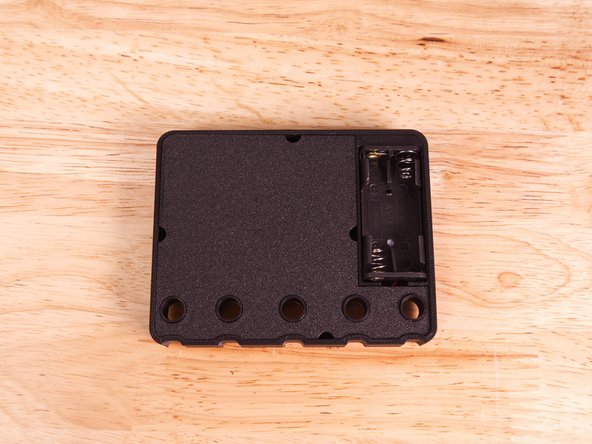
You can now add the back cover. It's just held in place with a friction fit.
-
There are a few half-circle cutouts along the edges to allow you to insert a tool and pry the back off if needed.
-
A few notes...
-
The "easy to remove" back cover, as well as the components which are easy to remove and put back, are due to this being an internal project we built for our trade show display.
-
We never really intended to create a rugged and polished device, but people kept asking us how they could make their own, so we threw this guide together and released the files.
-
We wanted to make it easy to open and get at the electronics for modifying and uploading new code, which we did many times!
-
-
-
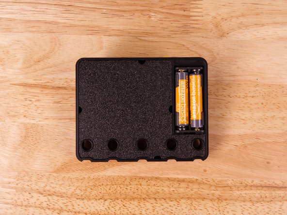
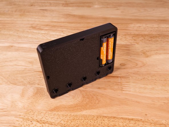
Put the batteries in place and the Micro:Bit should start showing icons and animations!
-
Wait... is there no on/off button!? Correct. Like all great(?) maker projects you have to pull out a battery to turn it off.
-
This is mainly due to the fact that when we use this for a trade show display it just runs all day long and we never need to turn it off. It's also one fewer components to solder into the circuit.
-
-
-
Your 3D Printed (Large) Micro:Bit is now complete!
-
Is it an exact replica? No...
-
Is it weird that it has a controller that is not a Micro:Bit inside? Maybe...
-
Is it still pretty darn cool? Yes!
-