Introduction
3D print an Arcade Button Enclosure so you can make a large arcade button compatible with Maker Tape.
Use the button in any paper circuits project where you need a button, or integrate it with Crazy Circuits projects by connecting it with Maker Tape.
Tools
Parts
-
-
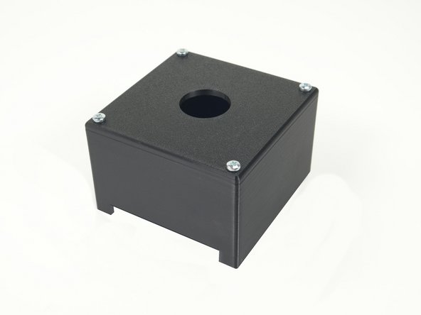
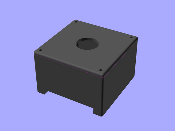
The Arcade Button Enclosure is printed in three parts, then assembled with hardware into a single unit.
-
Find the files in our GitHub repository: https://github.com/BrownDogGadgets/3D-Pr...
-
Or on Printables.com: https://www.printables.com/model/649397-...
-
-
-
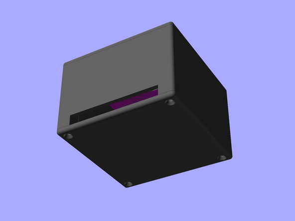
It's best to print the body upside down so you don't need to add supports for the cutout slot.
-
The top and bottom covers can be printed in either orientation.
-
Print them outward face down if your printer creates nice smooth surfaces on the bottom of prints.
-
-
-
Add the top cover to the body using 3mm screws.
-
3mm x 10mm screws work well, but you can use screws that are from 8mm to 12mm and they should also work.
-
-
-
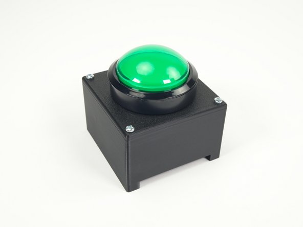
We've now got the top cover in place so we can add the arcade button.
-
We'll walk through those steps as we go.
-
-
-
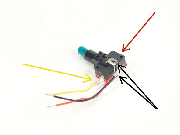
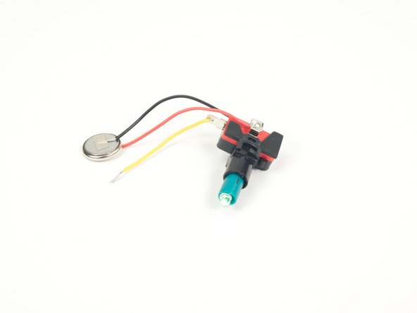
You will need to add 3 (or 4) wires to the switch and LED housing.
-
The Black wires goes to GND on the switch and to GND for the LED.
-
Note we have just 3 wires because we connected the black wire to GND for both the LED and switch together.
-
The Yellow wire goes to the NO contact on the switch. (Some switch will have a NO and NC contact, but the NO is typically closer to the bottom.)
-
The Red wire goes on the positive (other side) of the LED housing, opposite the black wire.
-
We recommend soldering the wires for the best connection but if you are unable to solder you can try to wrap them with Maker Tape around the terminals.
-
-
-
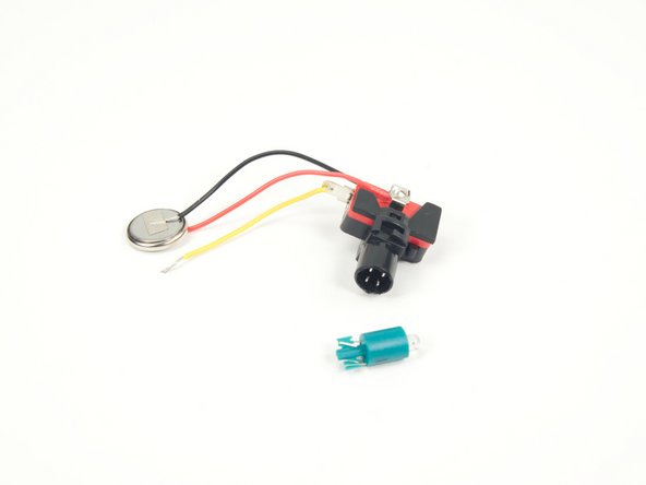
Use a CR2032 Battery to check if the LED lights up.
-
If it does not, pull it out, rotate it 180 degrees, and then reinsert it to see if that fixes it.
-
Unfortunately the LED may not be very bright since it will only be powered by 3 volts, but it can still be a nice indicator and does show up well in a darkened room.
-
-
-
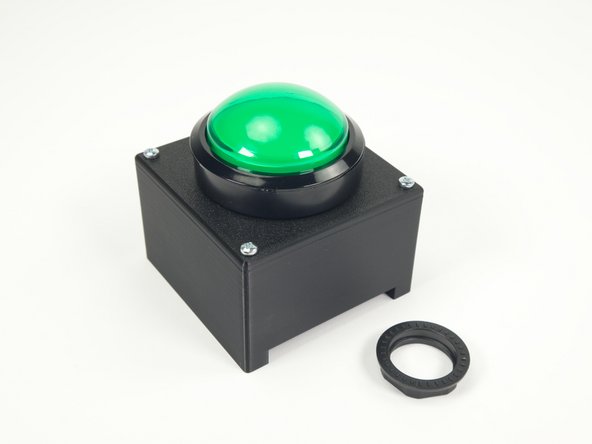
Insert the button through the hole on the top, and then screw the large plastic nut in place to secure the button.
-
We've aligned the white tabs so that one is closest to the side with the slot in the button enclosure.
-
-
-
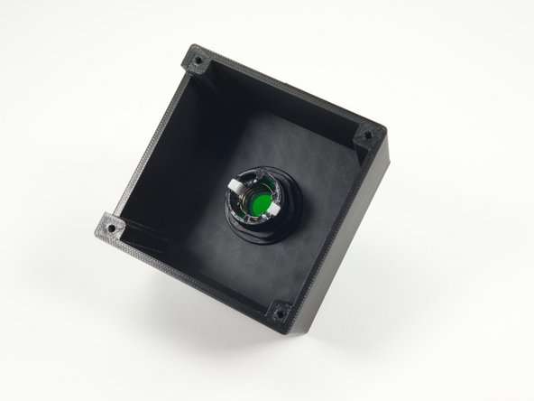
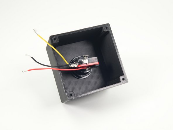
We can now add the LED/Switch to the arcade button by pushing it into place and rotating it to lock in.
-
We've positioned it so the wires can go out the slot of the printed enclosure.
-
-
-
To secure the bottom cover we used #4 screws.
-
These flat head #4 x 3/8" screws should fit perfectly.
-
-
-
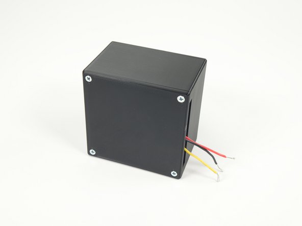
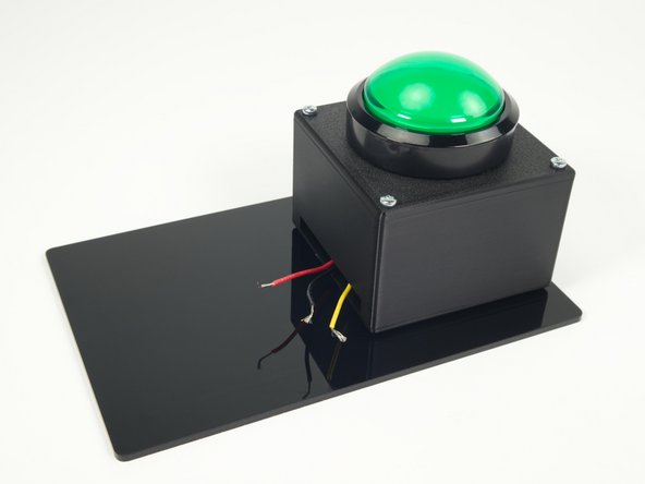
Okay! Our Arcade Button and 3D printed enclosure should be all assembled, we should have three (or four) wires sticking out of it, and it should be ready to go.
-
In the following steps we'll show you how prepare it for connecting to your circuit using Maker Tape.
-
Remember, the Black wire is GND, the Red wire is for the LED inside the button, and the Yellow wire is for the switch.
-
-
-
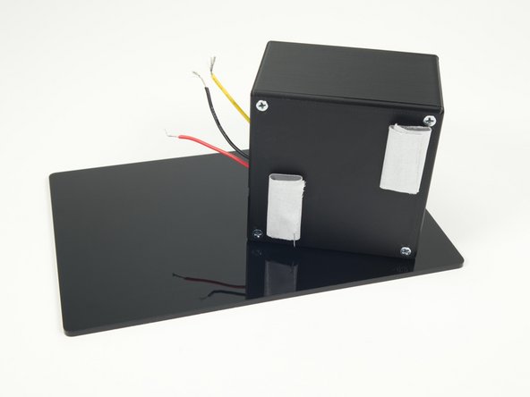
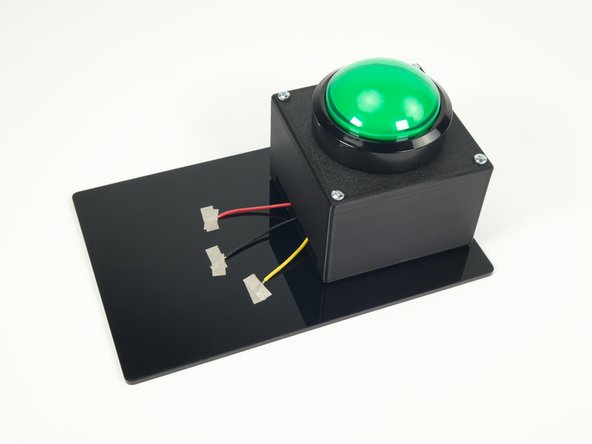
We added two large loops of tape to the button enclosure to stick it down to a plate.
-
We used gaff tape, but you can use masking tape, painter's tape, or whatever tape you have available.
-
For our plate we used a piece of acrylic but you can use cardboard, wood, or whatever (non-conductive material) you have available.
-
Once the button enclosure is stuck down to the plate just tape down the wires using Maker Tape and you're all set!
-
At this point our arcade button is very similar to our Cardboard Push Buttons except we've got an extra wire for the LED.
-
-
-
Ready for gently pressing or excitedly slamming!
-
We do love our Cardboard Push Buttons but with our weekly quiz game things were getting a bit heated and the cardboard buttons were starting to wear out, so these will make a great replacement.
-
And you can use these buttons for any paper circuits or Crazy Circuits project that uses Maker Tape to connect things.
-