
Introduction
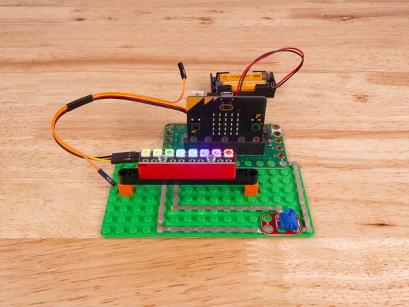
Connect a NeoPixel Stick and a Potentiometer to a Bit Board and control them with code.
We'll explore how to control an Addressable RGB LED Strip (also called "NeoPixels").
Video Overview
-
-
The magical thing about these “Individually Addressable” LEDs is that you don’t have to connect each LED to an individual pin on your micro:bit, you just need one signal wire along with power (Positive and Negative) to light things up.
-
So let's get connected! If you turn the NeoPixel Strip over you'll see labels for the three pins. You should see IN, VCC, and GND.
-
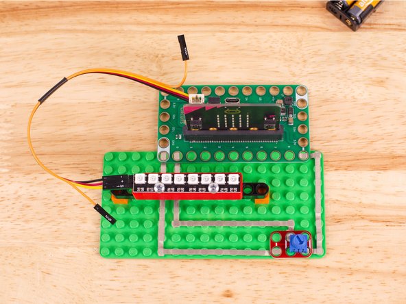
Use the Crazy Circuits Ribbon Cable to connect the NeoPixel Strip to the Bit Board.
-
The end with S1, +, and - can plug directly into the Pin 13 row (make sure S1 goes into 13) and the other end should plug into the NeoPixel Strip as shown.
-
We only need three wires for the NeoPixel Strip so you can leave S2 (the Orange wire) unconnected.
-
We'll also connect a potentiometer using Maker Tape. Connect it to GND, Pin 0, and 3V. (The center hole connects to Pin 0.)
-
-
-
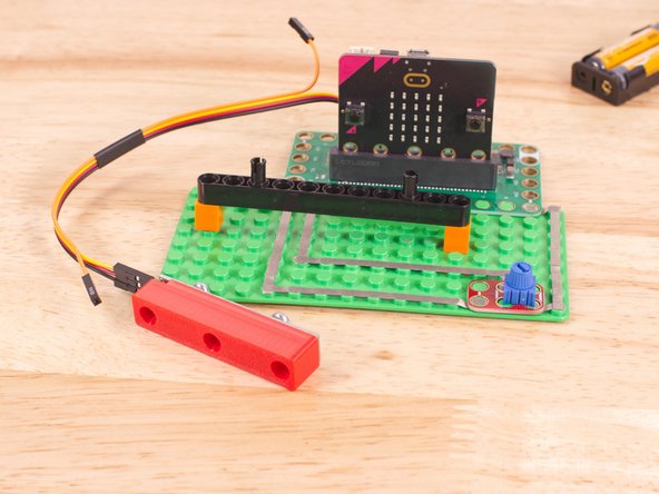
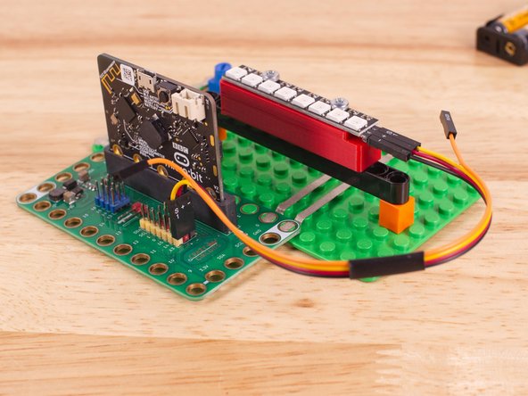
To mount the NeoPixel Stick in place we used our NeoPixel Beam Holder with a long Technic Beam and two 1x1 LEGO bricks.
-
You can always use rubber bands, tape, or some other method.
-
The important thing is to make sure the connector is on the left hand side so the number index for the NeoPixel strip makes sense.
-
-
-
If you've never used a micro:bit before you'll want to check out this guide: Bit Board V2 Setup and Use
-
We're going to load the following code for our NeoPixel Rainbow Steps program: https://makecode.microbit.org/_PXP3pzcsd...
-
We'll once again map the input from the potentiometer to a smaller scale. While the input will be from 0 to 1023 our output will be from 0 to 8. This effectively turns the potentiometer into a multi-position switch.
-
We will rotate the lit up pixels (using the show rainbow function) anywhere from 0 to 8 steps.
-
-
-
Once the code is loaded it should start running immediately.
-
You can power the micro:bit via the USB cable you used to load the code or you can use a battery pack plugged into the Bit Board.
-
With the potentiometer turned all the way anti-clockwise you'll see that the pixels do not move.
-
If you rotate the potentiometer all the way clockwise it will also appear that the pixels are not moving... But! They are moving, just 8 steps at a time, which means they appear to not be moving.
-
With the potentiometer all the way anti-clockwise start to turn the potentiometer slowly in the clockwise direction and you'll see the pixels move. First one step, then two, then three, etc...
-
When you get past the halfway point on the potentiometer the pixels may appear to start moving backwards, but they are not!
-
If the pixels appear to be moving backwards what we are seeing is sometimes call the Wagon-wheel effect which is usually related to film frames and rotating objects.
-
-
-
Follow along with our recorded Live Stream!
-
You can watch the full video of us walking through this project, along with explaining and exploring the code: https://www.youtube.com/live/-2ECPBjKX1Q
-


Attached Documents
