
Introduction
Build your own Wireless Game Show Buzzer System with large "slammer" buttons for up to four teams/players. Powered by multiple micro:bits and Bit Boards.
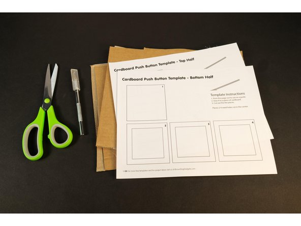
For this project we are using these Cardboard Buttons made with Maker Tape. Follow the guide and build your own so you can use them with this project!
Video Overview
Featured Document
-
-
This is an alternative version of our Game Show Buzzer System that uses Maker Tape (and/or wire) to connect the buttons.
-
You don't need to be familiar with the guide for the Game Show Buzzer System but it's there if you want to peruse it.
-
For this version we've gone wireless thanks to the built-in radio found on each micro:bit
-
You do need more micro:bit boards (and Bit Boards) for this build, but if you've got a classroom set, you'll have most of what you need.
-
-
-
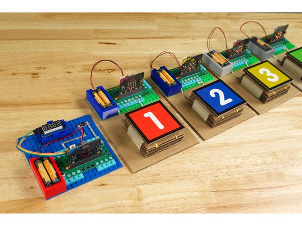
Our Wireless Game Show Buzzer System consists of four buttons for teams/players to use to "buzz in" so they can answer the question, and a fifth button on the Host Unit to reset the system for each round.
-
Each button is connected to its own micro:bit and Bit Board. Up to four for the teams, and one for the host.
-
You can play with less than four team if desired as well. Just use/make less team units.
-
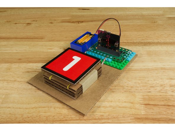
Half the fun (and work) of this project is building the cardboard buttons. You can use any sort of button but using big "slammer" style buttons makes playing the game a blast!
-
Check out the guide for Cardboard Buttons so you can make you own!
-
-
-
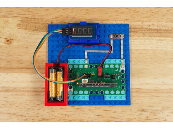
Build the Host Unit using the diagram as a guide.
-
The 7 Segment Display is optional. It just displays the team number like the built-in LED matrix of the micro:bit does, but we added it after testing when our host said they wanted another display behind the Host Unit so they could see it too.
-
The reset button is also optional. It's connected to Pin 11, which is the same pin the B button on the micro:bit is connected to. You can use the built-in B button or choose to add a separate (easier to press) button if desired.
-
For the Host Unit use a micro:bit V2 with a built-in speaker so it will beep during the countdown.
-
While you can power the micro:bit and Bit Board using a 2 AAA Battery Pack will allow the unit to be portable and placed wherever desired.
-
-
-
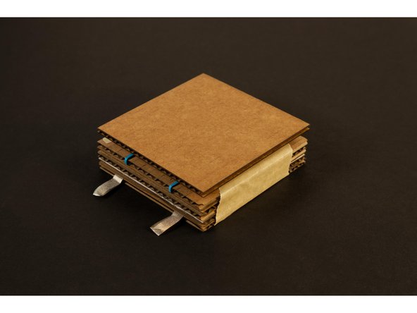
We could use Crazy Circuits buttons for this project (and we did for the host unit reset button) but half the fun of doing your own game show is smashing the buzzer!
-
Since we already have a guide for Cardboard Buttons we thought we'd make some to use with our game system.
-
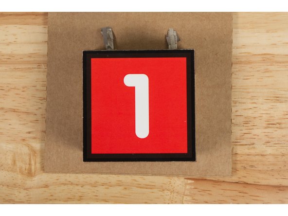
We also included the colorful number designs we used on the top of our buttons in case you want to print a version for yourself. You can find them the PDF file included with this guide.
-
We just printed them and stuck them down to our Cardboard Buttons with some blue painter's tape so we could remove them easily but you can also glue them in place.
-
-
-
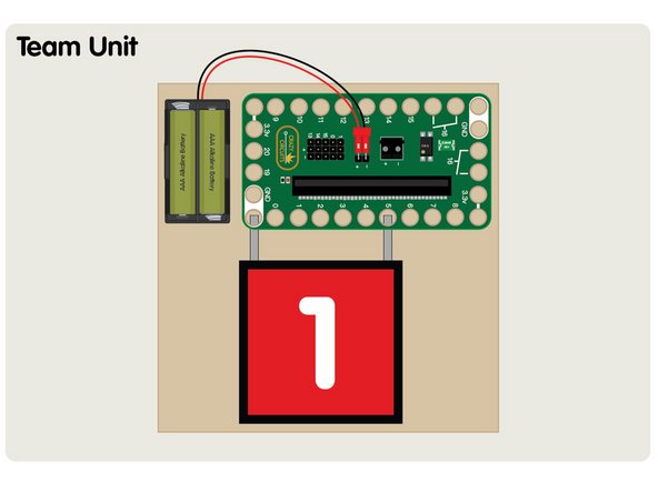
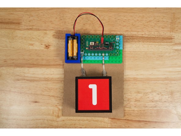
For each of the team buttons you’ll need to connect a button to GND and Pin 5.
-
Each Team Unit will need to be programmed separately so each sends a unique value (the team number) to the Host Unit. (Besides setting one variable, the code is the same for each team unit.)
-
We stuck each Team Unit down to a piece of cardboard to make them a bit more portable. You could also build the whole thing onto a LEGO baseplate as well.
-
-
-
If you've never used a micro:bit before you'll want to check out this guide: Bit Board V1 Setup and Use
-
We're going to load the following code for our GBSW Host program: https://makecode.microbit.org/_TKV76JPok...
-
Remember that if you want to change the countdown time you just need to edit the countdownSeconds variable in the code.
-
-
-
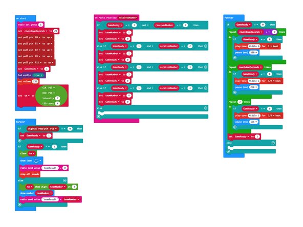
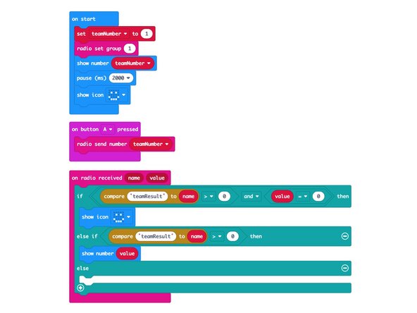
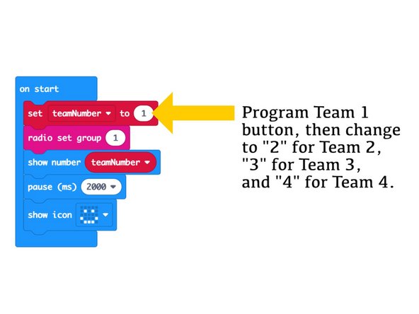
Next we'll load the following code for our GBSW Team program: https://makecode.microbit.org/_9KVVcKXwq...
-
Once you load the code for the Team 1 button you'll need to change the teamNumber variable to 2 and program the Team 2 button, and so on...
-
Make sure each button has a different number or they will conflict when playing the game!
-
Once you program all of the team buttons you are ready to try them out!
-
-
-
To test a Team Unit you can power it up and it should show the corresponding number on the built-in LED matrix and then show the smiley face when it's ready to go.
-
Each Team Unit will show a different number... If any two show the same you may need to make sure you've loaded the correct code onto each one.
-
-
-
We're ready to test the whole system!
-
Make sure the code is loaded onto each micro:bit and you've got power going to all the units.
-
When you press a button it should show the corresponding number on all of the Team Units (as well as the 7 Segment Display on the Host Unit if you've got it connected.)
-
You'll also hear the host unit beeping the countdown for the team to answer the question.
-
When the time is up (or the host resets the system) all units will show the smiley face again letting you know they are ready to go again.
-
-
-
Now that you have a Wireless Game Buzzer System what will you do with it? You can host a quiz in your classroom but you might also come up with other uses.
-
Maybe you could use this in a race where the runners need to reach the end of the course and press the button. You'll know who got there first!
-
You can also make changes to the buttons. You can use other buttons. Maybe you like the Crazy Circuit Jumbo Pushbutton Chip or maybe you want students to design their own buttons. (Check our Basic Paper Circuits guides for some ideas.)
-


Attached Documents
