
Introduction
Build your own Game Show Buzzer System with large "slammer" buttons for up to four teams/players. It's all powered by a micro:bit and our Bit Board.
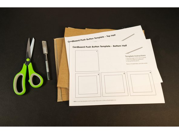
For this project we are using these Cardboard Buttons made with Maker Tape. Follow the guide and build your own so you can use them with this project!
Video Overview
Featured Document
-
-
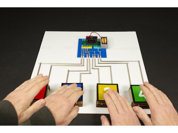
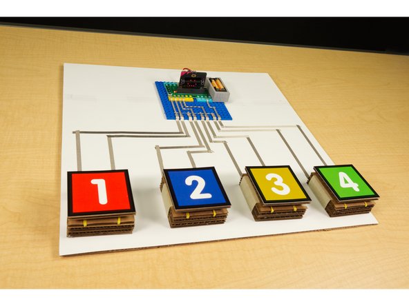
Our Game Show Buzzer System consists of four buttons for teams/players to use to "buzz in" so they can answer the question, and a fifth button to reset the system for each round.
-
The Bit Board allows all of the buttons to be connected with Maker Tape, and the system can run using the 2 AAA Battery Pack that comes with the Bit Board.
-
Half the fun (and work) of this project is building the cardboard buttons. You can use any sort of button but using big "slammer" style buttons makes playing the game a blast!
-
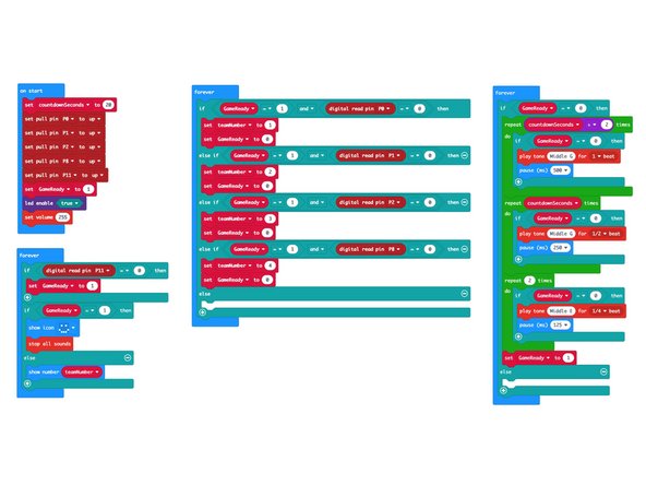
We highly recommend you download the PDF file for this guide. It goes into great detail about the code for this project, and while you don't have to understand the code to use it, it may be helpful when you write your own code.
-
Check out the guide for Cardboard Buttons so you can make you own!
-
-
-
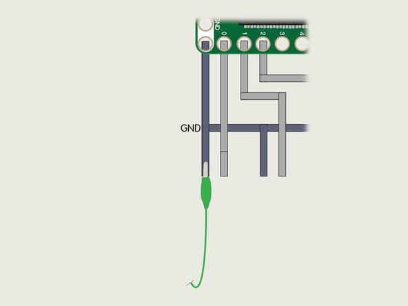
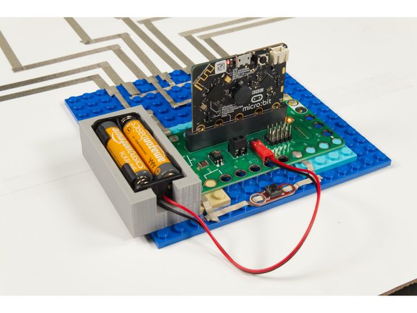
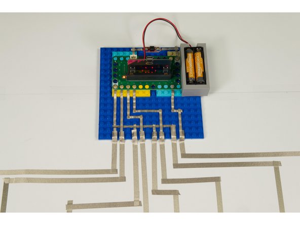
Build your circuit as shown in the diagram. (You can see the circuit diagram in greater detail in the PDF file included with this guide.)
-
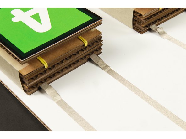
The important thing to note about this circuit is that the Maker Tape for the Ground connections goes beneath the Maker Tape for the pins, but it does not touch.
-
We run the Ground tape between the LEGO baseplate studs and we run the tape for the pins on top of the LEGO baseplate studs.
-
You can see an example of this method in the second photo.
-
We run each piece of tape to the edge of the LEGO baseplate to make it easy to attach our buttons in Step 4.
-
-
-
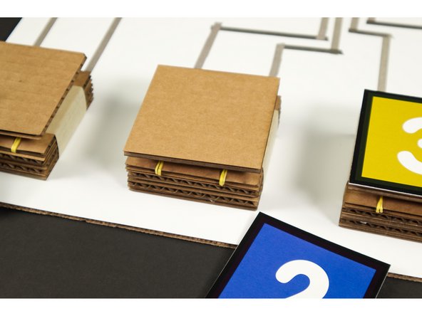
We could use Crazy Circuits buttons for this project (and we did for the reset button) but half the fun of running your own game show is smashing the buzzer!
-
Since we already have a guide for Cardboard Buttons we thought we'd make some to use with our game system.
-
We also included the colorful number designs we used on the top of our buttons in case you want to print a version for yourself. You can find them the PDF file included with this guide.
-
We just printed them and stuck them down to our Cardboard Buttons with some blue painters tape so we could remove them easily.
-
-
-
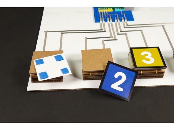
There are a few options to connect your buttons. For our demo we put the entire thing on a piece of cardboard and used some 1/4" wide Maker Tape, but there are other methods.
-
Maker Tape is awesome for many things, but you can also use plain old wire. As long as the insulation is stripped from the wire you can tape it down to the contact points for the circuit.
-
Check out our Tape to Wire Connections guide for tips on wire connections.
-
You can also use alligator clips to connect things. They're easy to use and if you don't have wire (and a wire stripper) available can work in a pinch.
-
If using alligator clips be careful not to short out your circuit with the metal clips on the end. Use the kind that have a rubber boot covering the metal clip.
-
If you do go with the Maker Tape method you can run the tape down along a table surface for a much longer length than we used for our demo. Just make sure you don't cross any of the different tape pieces and cause a short circuit!
-
-
-
If you've never used a micro:bit before you'll want to check out this guide: Bit Board V1 Setup and Use
-
We're going to load the following code for our Game Buzzer System program: https://makecode.microbit.org/_Ywd68x9b6...
-
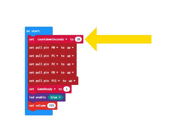
Remember that if you want to change the countdown time you just need to edit the countdownSeconds variable in the code.
-
-
-
Now that you've got your buttons built and connected, and you've uploaded the code it's time to test it out!
-
Press one of the buttons and make sure the micro:bit shows the corresponding number on the built-in LED matrix on the front.
-
Try each of the buttons, including the reset button (which should be pressed while the beeping countdown is happening.)
-
If all buttons work as expected you are ready to play! If something isn't working, double check all of your connections, make sure all the Maker Tape and/or wires, alligator clips, etc are pressed down securely.
-
You can power the system using the USB cable you plugged into the micro:bit to load the code, or you can use a 2 AAA Battery Pack plugged into the Bit Board. Either method will work.
-
-
-
Let's play! Your Game Host will be in charge of asking questions and pressing the reset button (if needed).
-
The players will be in charge of smashing their buttons and answering questions.
-
Any rules or specifics of the game are up to you. We've found that some teachers do things just a little bit differently in their classroom, but most do things in a pretty common fashion, and this system should work fine for most needs.
-
If you want something a little different you can change the code and adjust it to suit your needs.
-
The important thing is that making this system should be fun and educational. There are elements of mechanical, electrical, and computer engineering you can highlight when creating this project.
-
-
-
As we mentioned you can make any changes you want to the code for this project, but...
-
You can also make changes to the buttons. You can use other buttons. Maybe you like the Crazy Circuit Jumbo Pushbutton Chip or maybe you want students to design their own buttons. (Check our Basic Paper Circuits guides for some ideas.)
-
You could use an LED instead of the speaker for a visual countdown of time remaining. Or you could connect four LEDs and use those instead of the built-in LED matrix.
-
-
-
We don't just post these projects... we use them!
-
After our first test in the real world we found that the host wanted to sit behind the micro:bit, but then could not see the number on the LED matrix side that was facing the players.
-
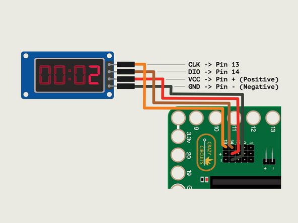
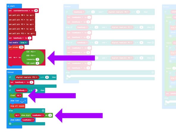
We solved that by adding a 7 Segment Display to the system that can be placed behind the micro:bit, right next to the reset button.
-
The updated code is called Game Buzzer System 7 Segment: https://makecode.microbit.org/_PbKT624Mw...
-
You can use this code even without the 7 Segment Display added. We just put in three extra blocks of code to support the extra display.
-
To use the display with the Bit Board just connect CLK into Pin 13, DIO into Pin 14, VCC into the + (positive) column, and GND into the - (negative) column using four Female/Female Jumper Wires.
-
If you have any problems adding the 7 Segment Display, check Step 2 in our Binary Math Game guide.
-


Attached Documents
