Introduction
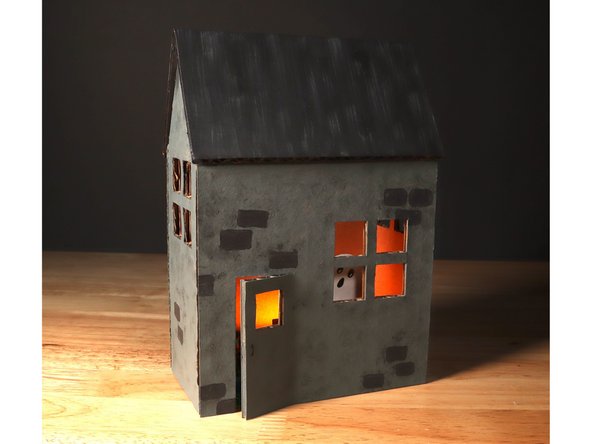
This Haunted House uses a 270˚ Servo, NeoPixel Strip, micro:bit and Bit Board to create a festive Halloween scene.
Tools
Optional Tools


Video Overview
Featured Document
-
-
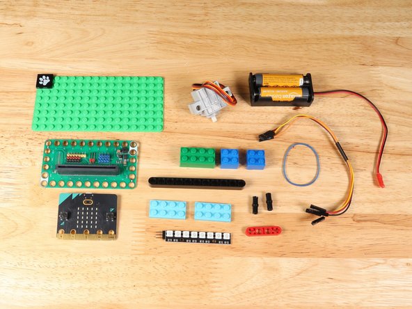
Gather the supplies for the circuitry inside the Haunted House.
-
The LEGO parts can easily be swapped for similar LEGO bricks/beams that you have on hand with minor adjustments to the layout.
-
-
-
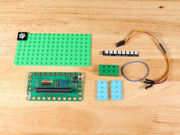
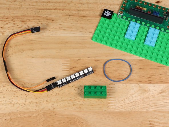
To connect the NeoPixel Strip to the project you will need a Crazy Circuits Ribbon Cable, a rubber band, and some LEGO bricks.
-
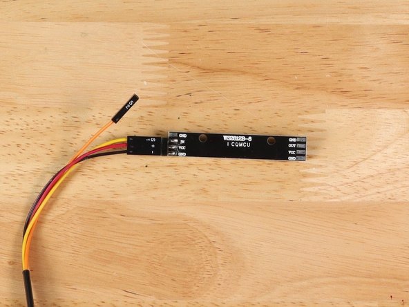
If you turn the NeoPixel Strip over you'll see labels for the three pins. You should see IN, VCC, and GND.
-
Using the end of the Crazy Circuits Ribbon Cable with all four wires separate, connect S1 to IN, + to VCC, and - to GND.
-
We only need three wires for the NeoPixel Strip so you can leave S2 (the Orange wire) unconnected.
-
-
-
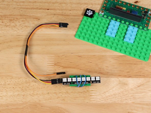
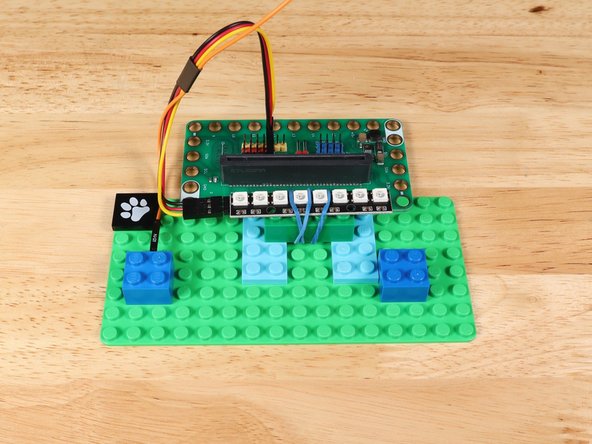
Attach the NeoPixel Strip to a LEGO brick with a rubber band.
-
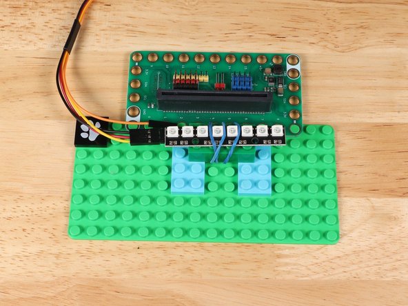
Connect the brick to a couple other LEGO parts on the baseplate so the rubber band doesn't get in the way.
-
Placement of the bricks and NeoPixel Strip can be adjusted based on your desired needs.
-
-
-
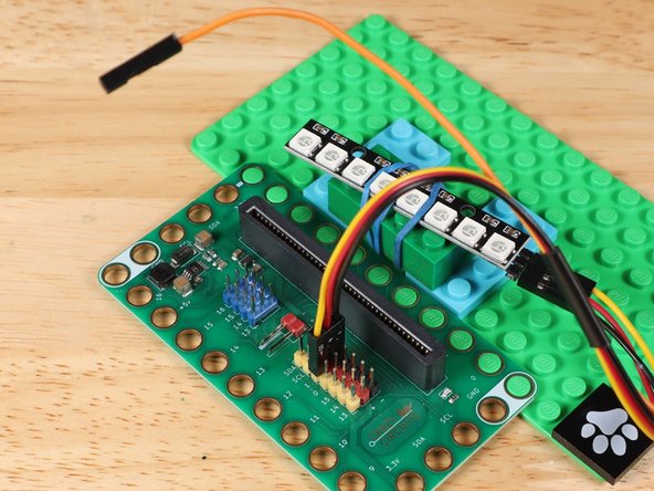
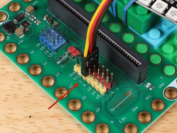
The end with S1, +, and - can plug directly into the Pin 1 row (make sure S1 goes into 1).
-
We only need three wires for the NeoPixel Strip so you can leave S2 (the Orange wire) unconnected.
-
-
-
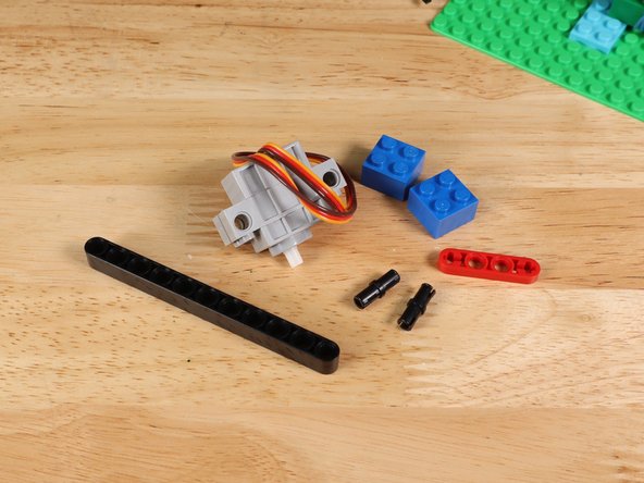
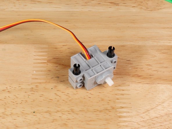
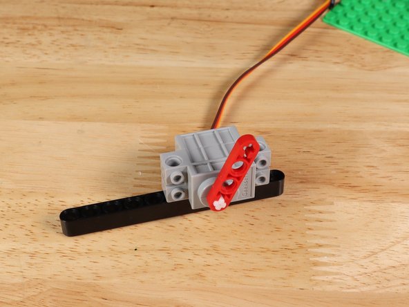
Insert two black pins on the side of the servo where the wires connect.
-
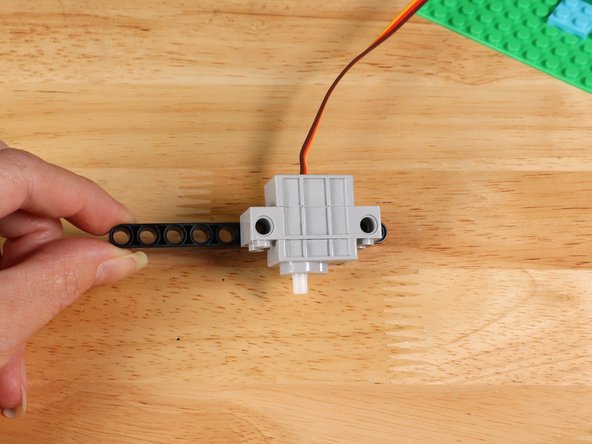
Connect the servo to a LEGO technic beam with the wires at the bottom. In this guide we used an 11-hole long beam. You can also use a different size and modify accordingly.
-
-
-
Attach a LEGO half beam with axle holes onto the shaft of the servo. The ghost will be taped onto this in a later step.
-
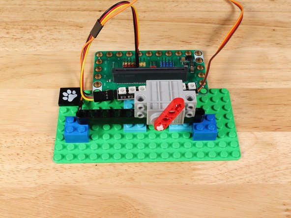
Using some bricks, connect the beam with servo attached to the baseplate.
-
You can adjust the placement of the beam on the shaft, servo on the beam, and beam on the baseplate to make the assembly line up the way you want.
-
-
-
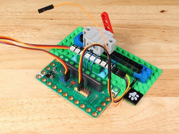
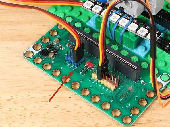
The 270 Degree Servo Motor has a 3-wire connector on the end that can plug directly into the pins on the back of the Bit Board.
-
The Blue Pins on the Bit Board provide extra power (5 volts instead of 3 volts) by boosting the voltage coming from the battery pack. This helps improve servo performance, especially with multiple servos.
-
Make sure the Orange Wire is closest to the number 13 for the Pin 13 column.
-
Then the Brown Wire should be closest to the micro:bit (in the - row) and the Red Wire will be in the middle (the +5v row).
-
-
-
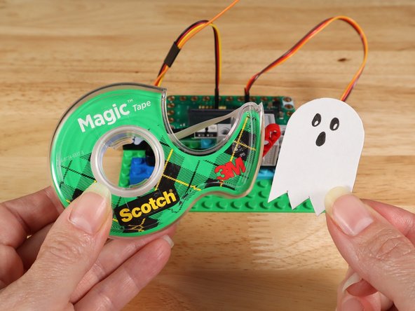
Cut out the ghost from the template or make your own.
-
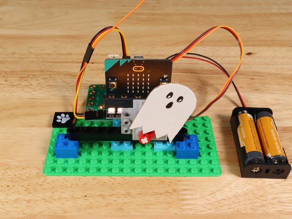
Attach the ghost to the half beam on the servo using tape.
-
Once code is added to your build, the placement of the half beam on the servo may need to be adjusted. You can simply pull the beam off the shaft and reconnect it once the servo is oriented correctly.
-
-
-
If you've never used a micro:bit before you'll want to check out this guide: Bit Board V2 Setup and Use
-
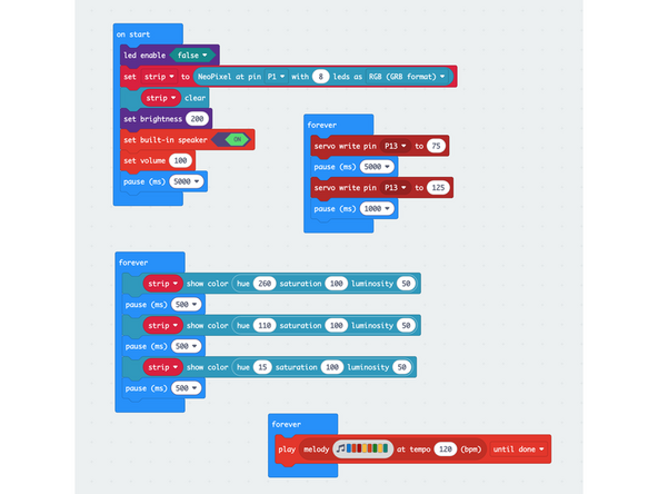
We're going to load the following code for our Haunted House: https://makecode.microbit.org/S57411-058...
-
-
-
Once the code is loaded onto the micro:bit and power is supplied to the project there will be a 5 second delay.
-
After the delay, music will begin to play directly from the onboard speaker, the NeoPixel Strip will rotate through 3 colors, and the servo will switch between two distinct positions.
-
You can modify the code in many different ways to meet your needs. Some options for modifications are the colors on the NeoPixel, the music playing, or the pauses for servo.
-
-
-
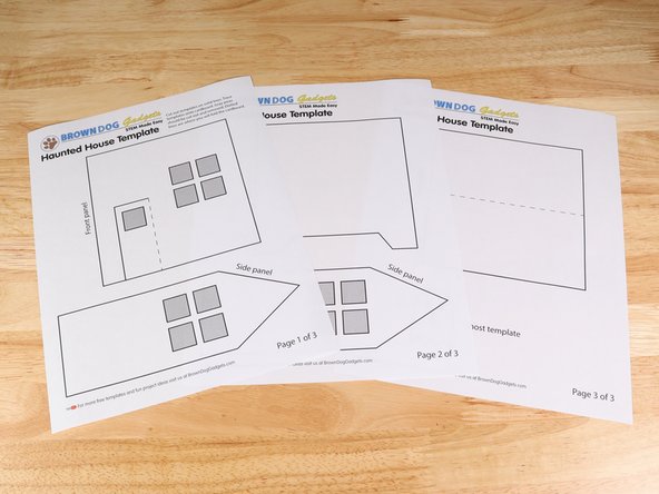
Cut out the template parts.
-
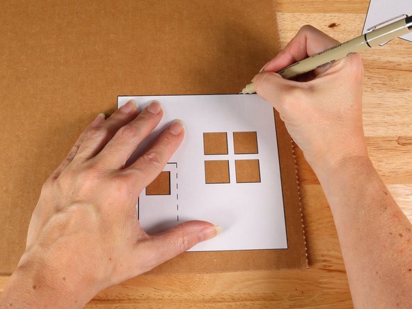
There are two different ways that we have found helpful when cutting out the house parts:
-
You can trace the template parts onto the cardboard with a pen or marker.
-
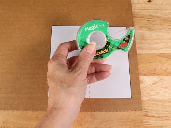
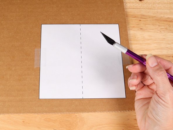
You can also tape the template right onto the cardboard and cut around the edges of the template.
-
-
-
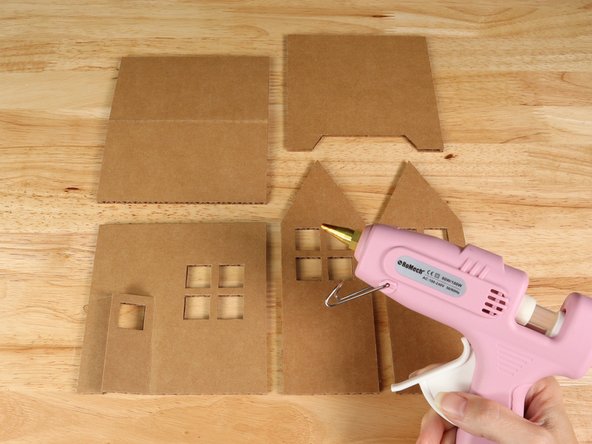
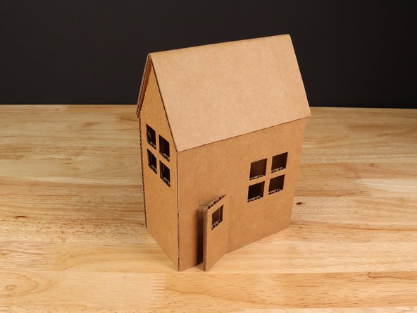
Carefully cut out all 5 panels for the house and assemble using hot glue.
-
-
-
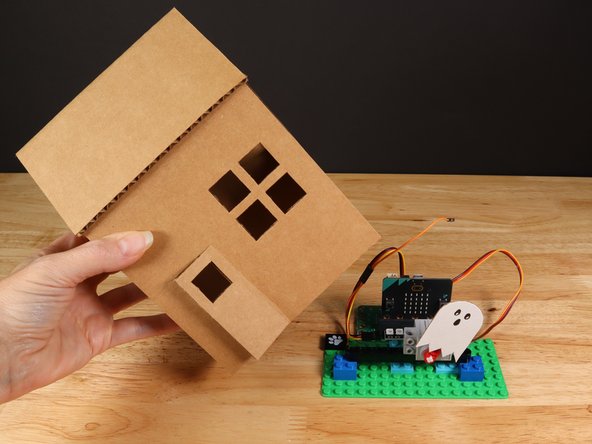
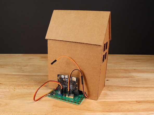
The house should fit around the perimeter of the baseplate.
-
You may need to adjust the wires so they fit under the back panel of the house.
-
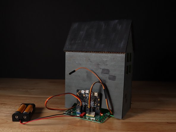
The micro:bit and Bit Board will be on the outside of the Haunted House in the back.
-
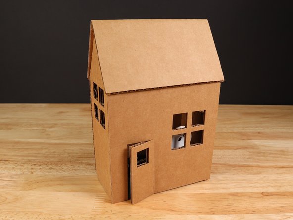
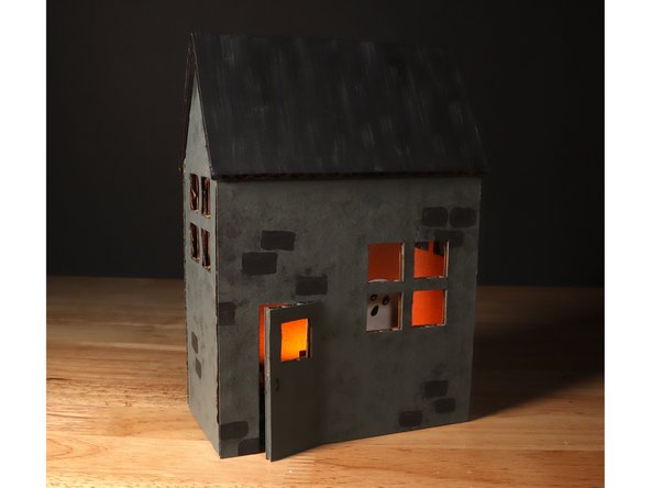
If you can't see the ghost through the window or door adequately, you can change the location of the servo on the beam as a quick adjustment.
-
-
-
Use paint, markers, or colored pencils to decorate your Haunted House!
-
The inside of the Haunted House is not painted. The brown of the cardboard is a great backdrop for the different colors we are using on the NeoPixel Strip.
-
-
-
Show off your Haunted House with spooky pride!
-
Attached Documents